
Optical-cmos-coupler
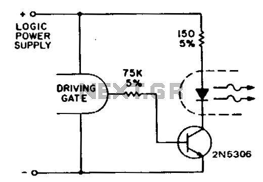
Standard CMOS logic operates with supply voltages as low as 3 V and is specified for a maximum current sinking/sourcing capability of 30 pA. To drive the infrared emitting diode (IRED) when utilizing CMOS to control an optocoupler, it is necessary to incorporate a buffer transistor to provide the required current. Similar to low output TTL families, the H74A output can drive multiple CMOS gate inputs or a standard TTL input with the appropriate biasing of the IRED. A single logic stage is sufficient to activate the IRED. This circuit is designed to establish worst-case drive criteria for the IRED across logic supply voltages ranging from 3 V to 10 V. However, utilizing higher value resistors for elevated supply voltages can lead to reduced power dissipation. In such cases, the worst-case drive to the IRED must account for the minimum supply voltage, minimum temperature, maximum resistor tolerances, gate saturation resistance, and the saturation voltages of the transistor. For the H74 devices, the minimum IRED current under worst-case conditions, with a zero logic state output from the driving gate, is 6.5 mA, while for the H11L1, it is 1.6 mA.
The circuit in question utilizes CMOS logic to interface with an optocoupler via an IRED, requiring careful consideration of current requirements and voltage levels. The buffer transistor serves as an intermediary to ensure that the current supplied to the IRED meets the necessary specifications for reliable operation. The H74A output is capable of driving multiple CMOS inputs or a TTL input, contingent upon proper biasing of the IRED, highlighting the versatility of this configuration.
The design must address various operational parameters, including the worst-case drive conditions, which are critical for ensuring the IRED operates effectively across the specified voltage range. This includes evaluating the impact of temperature variations, resistor tolerances, and the saturation characteristics of the transistors involved. The worst-case scenario dictates that the minimum current supplied to the IRED must be maintained, particularly when the driving gate output is at a zero logic state.
In practical applications, selecting appropriate resistor values is essential for managing power dissipation. Higher resistance values can reduce power consumption at elevated supply voltages, but this must be balanced against the need to provide sufficient current to the IRED, particularly under unfavorable conditions. The specified minimum IRED currents for the H74 and H11L1 devices indicate the importance of understanding the specific requirements for different components to ensure optimal performance in the overall circuit design.Since standard CMOS logic operates down to 3-V supply voltages and is specified as low as 30 p.A maximum current sinking/sourcing capability, it is necessary to use a buffer transistor to provide the required current to the IRED if CMOS is to drive the optocoupler. As in the case of the low output TTL families, the H74A output can drive a multiplicity of CMOS gate inputs or a standard TTL input given the proper bias of the IRED.
A onelogic stage drives the IRED on. This circuit will provide worst-case drive criteria to the IRED for logic supply voltages from 3 to 10 V, although lower power dissipation can be obtained by using higher value resistors for high supply voltages. If this is desired, the worst-case drive must be supplied to the IRED with minimum supply voltage, minimum temperature and maximum resistor tolerances, gate saturation resistance, and transistor saturation voltages applied.
For the H74 devices, minimum IRED current at worst-case conditions, zero logic state output of the driving gate, is 6. 5 mA and the HllLl is 1.6 mA. 🔗 External reference