Optically-int-erfaced-ring-detector

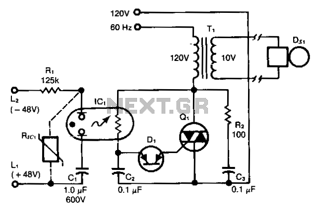
This ring detector, utilizing a neon-LDR (light-dependent resistor) optocoupler, simplifies interfacing with telephone lines.
The ring detector circuit is designed to detect the ringing signal from telephone lines, which typically operates at a frequency of 20 Hz to 25 Hz with a voltage of approximately 90V AC. The use of a neon-LDR optocoupler in this application provides electrical isolation between the high-voltage telephone line and the low-voltage control circuitry, ensuring safety and preventing damage to sensitive components.
In this circuit, the neon bulb serves as a light source that illuminates the LDR when the telephone line rings. The LDR's resistance decreases significantly in response to the light emitted by the neon bulb, allowing current to flow through the circuit. This change in resistance can be used to trigger a transistor or a microcontroller, which can then activate other components, such as an LED indicator or a relay for further processing.
The design should include a series resistor to limit the current flowing through the neon bulb, protecting it from excessive current. Additionally, a capacitor may be included to filter out noise and provide a stable signal. Proper consideration must also be given to the layout of the circuit, ensuring that the high-voltage and low-voltage sections are adequately separated to maintain safety standards.
Overall, this ring detector is an effective solution for detecting ringing signals in telephone lines, offering a simple yet robust method for interfacing with telecommunication systems.This ring detector, utilizing a neon-LDR (light dependent resistor) optocoupler, simplifies inter facing with telephone Jines.