
Optoreflector
Optoreflector sensors consist of a matched infrared transmitter (LED) and an infrared receiver (typically a phototransistor) pair. These devices function by measuring the amount of light reflected into the receiver. Since the receiver is also sensitive to ambient light, optimal performance occurs when it is shielded from surrounding light, and when the distance between the sensor and the reflective surface is minimal. Infrared reflectance sensors are commonly employed to detect white and black surfaces, where white surfaces reflect well and black surfaces reflect poorly. In the mechatronics lab, the QRB1114 from Fairchild is utilized, which features four pins, with one pair connected to the LED and the other pair connected to the phototransistor. The circuit can be configured to detect objects directly in front of the QRB1114, with a potentiometer used to adjust for ambient lighting conditions. The output is an analog signal that varies with distance. The sensor performs best when partially shielded from ambient light. Two methods are available for processing the output: 1) additional circuitry can be constructed using a Schmitt trigger or a 555 timer to convert the output to a digital signal, or 2) an analog input can be used with a software threshold, which is a simpler approach. The program provided can be utilized to adjust voltage thresholds (using the relay block) and light sensitivity (by modifying the potentiometer). The circuit employs hardware to process the signal and utilizes the PC/104 stack’s digital input. Increasing the value of resistor R1 enhances sensitivity, but caution is advised as excessive sensitivity may allow ambient light to trigger the sensor. An XPC Target program is available to count the number of times the sensor is activated and display the count on a Seetron BPI-216 LCD. To implement this, the output from the circuit should be connected to channel 2 of the digital input on the breakout board, and pressing Bit 1 on the breakout board will reset the count. For an analog circuit, the Schmitt trigger from Example Digital Circuit 2 can be removed, allowing direct connection to the analog input on the breakout board. The ADC will output the nearest integer voltage of the input within the range of -10V to 10V, with this circuit typically yielding a voltage between 0V and 5V.
Optoreflector sensors are integral components in various applications, especially in automation and robotics, where precise object detection is crucial. The QRB1114 model, with its robust design and compatibility with various circuits, serves as a reliable choice for detecting surfaces based on reflectivity. The implementation of a potentiometer allows for fine-tuning of the sensor's sensitivity, adapting it to different lighting environments.
In practical applications, it is essential to consider the distance between the sensor and the reflective surface, as this directly impacts the output signal. The use of a Schmitt trigger in digital applications provides a clear transition between high and low states, which can be beneficial in noisy environments. Alternatively, the analog processing method allows for more nuanced readings, with the ability to monitor varying levels of reflectance.
The integration of the sensor with a microcontroller or a PC/104 stack enhances its functionality, enabling real-time data processing and display. The ability to reset the count via the breakout board adds a layer of interactivity, making the setup ideal for experiments and demonstrations.
In summary, the QRB1114 optoreflector sensor is a versatile component that can be tailored to meet specific detection needs, with both digital and analog processing options available for various applications. Proper shielding from ambient light and careful adjustment of sensitivity are key to achieving optimal performance.Optoreflector sensors contain a matched infrared transmitter (LED) and infrared receiver (usually a phototransistor ) pair. These devices work by measuring the amount of light that is reflected into the receiver. Because the receiver also responds to ambient light, the device works best when well shielded from abient light, and when the distance b
etween the sensor and the reflective surface is small (the graph below shows how distance affects the output value). IR reflectance sensors are often used to detect white and black surfaces. White surfaces generally reflect well, while black surfaces reflect poorly. In the mechatronics lab, we have the QRB1114 ( datasheet ) from Fairchild, shown below. It has four pins, with the first pair connected to the LED and the second pair connected to the phototransistor.
The circuit below can be used to detect objects directly in front of the QRB1114. The potentiometer must be used to adjust for ambient lighting conditions. The output is an analog signal like the one at the top of the page - dependent on distance. The sensor works best when it is at least partially-shielded from ambient light. There are two ways to process the output. 1) build extra circuitry using a schmitt trigger or 555 timer to turn the output into a digital output. 2) Use an analog input and use a software threshold. The second way is easier and works well. Start with the program below to adjust your voltage thresholds (using the relay block) and light sensitivity (by adjusting the potentiometer).
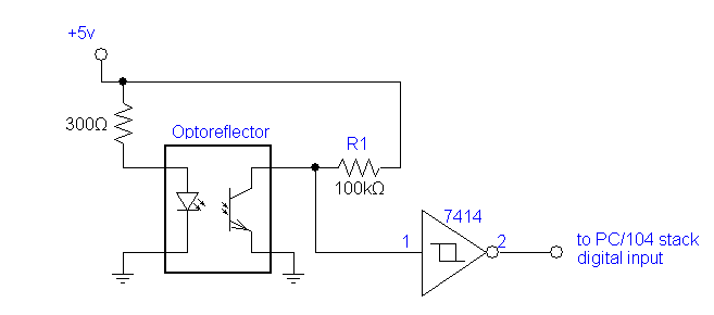
The circuit below uses hardware to process the signal and uses the PC/104 stack`s digital input. Increasing the value of the resistor R1 will increase the sensitivity, and vice versa. Beware that if you make the sensor too sensitive, ambient light will be able to trip the sensor. The following XPC Target program will count the number of times the sensor is tripped, and print it to the Seetron BPI-216 LCD. To use it, plug the output of the ciruit above into channel 2 of the digital input on the break-out board.
Pressing Bit 1 on the break-out board will reset the count. To make an analog circuit, just take out the Schmitt trigger from Example Digital Circuit 2, and connect the input directly to the analog input on the break-out board. The ADC will output the closest integer voltage of the input between -10V and 10V. For this circuit, the voltage will fall between 0V and 5V. 🔗 External reference
Optoreflector sensors are integral components in various applications, especially in automation and robotics, where precise object detection is crucial. The QRB1114 model, with its robust design and compatibility with various circuits, serves as a reliable choice for detecting surfaces based on reflectivity. The implementation of a potentiometer allows for fine-tuning of the sensor's sensitivity, adapting it to different lighting environments.
In practical applications, it is essential to consider the distance between the sensor and the reflective surface, as this directly impacts the output signal. The use of a Schmitt trigger in digital applications provides a clear transition between high and low states, which can be beneficial in noisy environments. Alternatively, the analog processing method allows for more nuanced readings, with the ability to monitor varying levels of reflectance.
The integration of the sensor with a microcontroller or a PC/104 stack enhances its functionality, enabling real-time data processing and display. The ability to reset the count via the breakout board adds a layer of interactivity, making the setup ideal for experiments and demonstrations.
In summary, the QRB1114 optoreflector sensor is a versatile component that can be tailored to meet specific detection needs, with both digital and analog processing options available for various applications. Proper shielding from ambient light and careful adjustment of sensitivity are key to achieving optimal performance.Optoreflector sensors contain a matched infrared transmitter (LED) and infrared receiver (usually a phototransistor ) pair. These devices work by measuring the amount of light that is reflected into the receiver. Because the receiver also responds to ambient light, the device works best when well shielded from abient light, and when the distance b
etween the sensor and the reflective surface is small (the graph below shows how distance affects the output value). IR reflectance sensors are often used to detect white and black surfaces. White surfaces generally reflect well, while black surfaces reflect poorly. In the mechatronics lab, we have the QRB1114 ( datasheet ) from Fairchild, shown below. It has four pins, with the first pair connected to the LED and the second pair connected to the phototransistor.
The circuit below can be used to detect objects directly in front of the QRB1114. The potentiometer must be used to adjust for ambient lighting conditions. The output is an analog signal like the one at the top of the page - dependent on distance. The sensor works best when it is at least partially-shielded from ambient light. There are two ways to process the output. 1) build extra circuitry using a schmitt trigger or 555 timer to turn the output into a digital output. 2) Use an analog input and use a software threshold. The second way is easier and works well. Start with the program below to adjust your voltage thresholds (using the relay block) and light sensitivity (by adjusting the potentiometer).
The circuit below uses hardware to process the signal and uses the PC/104 stack`s digital input. Increasing the value of the resistor R1 will increase the sensitivity, and vice versa. Beware that if you make the sensor too sensitive, ambient light will be able to trip the sensor. The following XPC Target program will count the number of times the sensor is tripped, and print it to the Seetron BPI-216 LCD. To use it, plug the output of the ciruit above into channel 2 of the digital input on the break-out board.
Pressing Bit 1 on the break-out board will reset the count. To make an analog circuit, just take out the Schmitt trigger from Example Digital Circuit 2, and connect the input directly to the analog input on the break-out board. The ADC will output the closest integer voltage of the input between -10V and 10V. For this circuit, the voltage will fall between 0V and 5V. 🔗 External reference