
Organ Sound Generator
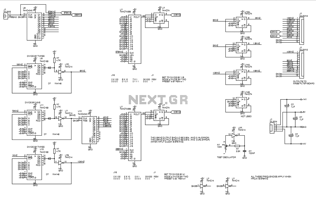
The circuit design described operates on the principles of harmonic generation and filtering to produce musical tones similar to those of a traditional tonewheel organ. The use of 74HC4046 phase-locked loops (PLLs) initially provided accurate prime harmonics; however, their limitations in frequency response and speed prompted a shift to a method utilizing frequency division. The high-frequency square wave oscillator serves as a clock source, with the fundamental frequency set at approximately 0.5 kHz. Programmable dividers are employed to derive the prime harmonics from this high-frequency source, allowing for the creation of additional harmonics through further division.
The square-wave outputs generated by this division process require conversion to sine waves for musical applications. This is accomplished through switched capacitor low-pass filters, which are synchronized with the high-frequency divider outputs to ensure optimal filtering characteristics. The corner frequency of each filter is carefully selected to align with the fundamental frequency of the signal being processed, ensuring minimal signal attenuation while maintaining a consistent output level.
The resulting sine wave outputs can be combined using front panel controls, akin to the drawbar system found in traditional organs. These controls include voltage control inputs for each harmonic, enabling dynamic manipulation of harmonic levels via an ADSR envelope generator or other control voltage sources.
Additionally, the vibrato effect is generated through a unique capacitive pickup mechanism that rotates within a screened enclosure. This design allows for a seamless transition between stationary capacitive pickup points, creating a Doppler effect as the pickup moves along a phase/delay line constructed from inductors and capacitors. This phase/delay line imparts both delay and phase shift to the audio signal, enhancing the overall tonal complexity and depth of the output, resulting in a rich and authentic sound reminiscent of classic tonewheel organs.Originally, the prime harmonics were generated with 74HC4046 PLLs which were spot-on accurate but would take some time to reach their final frequencies, especially when running at low frequencies. They also limited the useful frequency output range and I decided to dump them in favour of not quite spot-on divided-down frequencies.
It occurred to me that with a limited number of gears and teeth on the Hammond tonewheel generator, this might be authentic anyway. You can tell that the harmonics are not quite locked by looking at the output signal on an oscilloscope.
The principle of operation of a tonewheel organ is to have a fundamental output frequency for each note to which you can add upper and lower harmonics in varying amounts. This device uses a high frequency square wave oscillator which is divided down to provide the fundamental and even harmonics in square wave form.
The fundamental is nominally 0.5kHz. The prime numbered harmonics are approximated by dividing down from the H.F. clock with programmable dividers. The frequencies are thus not exact but are very close. The remaining harmonics can be generated by using dividers from the prime numbered harmonics. Note that because of this, the "prime numbered" harmonics are not necessarily really prime, but often multiples of them to facilitate this dividing method. e.g. the tenth harmonic is generated from a divider, and the 5th harmonic is then obtained with a simple flip-flop divider from the 10th harmonic.
These square-wave outputs need to be filtered to obtain sine waves. Switched capacitor low-pass filters are used to do this. The clock inputs of the filters are driven from one of the high-frequency divider outputs of the VCO. The particular divider output used is chosen based on getting the corner frequency close to the fundamental of the particular signal being filtered without causing too much attenuation.
As the filter corner frequency changes with the clock inputs, the filters will track the input signal and maintain a constant output level and filtering relationship. The sine wave outputs generated can be added together as desired using front panel level controls, in a similar way to that possible using the drawbars on a tonewheel organ.
The front panel controls also have voltage control inputs for each harmonic, allowing harmonic levels to be varied by an ADSR unit, or some other control voltage source. The vibrato unit in the original A-100 organ is based on a capacitive pickup which rotates inside a screened box around a set of stationary capacitive pickup points.
The result is that audio from each of the stationary inputs goes out to the rotating pickup in turn. Also, the switching from one 'emitter' to the next is a smooth transition; When the pickup is half way between the two sets of emitter plates it will be picking up approximately one half signal voltage from both. The emitter plates are connected to a phase/delay line made of same valued Ls and Cs, a bit like the very simple circuit model for coaxial cable.
The connections are made in such a way that when the scanner rotates, the pickup point moves up and down this line. As the audio input is at one end, and it suffers an approximate delay as it travels along, the pickup point experiences what is analogous to audio "doppler shift" as it traverses the line.
So when the pickup point travels away from the input, the frequency seen at the pickup is shifted downwards, and vice versa. It is worth noting that the phase/delay line is neither a true delay line nor a true phase shift. It is somewhere between the two, having a delay component and a phase shift component. The effect is rather like very dispersive co-ax. 🔗 External reference
Related Circuits
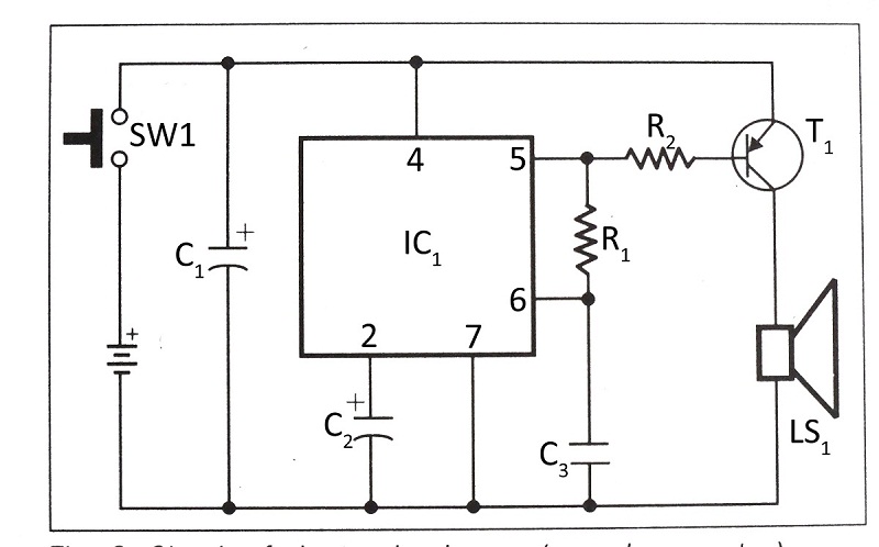
This document presents a verified circuit diagram for a simple, interesting, and cost-effective electronic clapper (sound generator) circuit, along with a description of its functionality. The electronic clapper circuit is designed to activate sound generation through the detection of sound...
The 4027 is a dual JK flip-flop that features independent clock, set, and reset inputs for each flip-flop, making it suitable for toggle, register, and control functions. It is capable of driving two low-power TTL loads and employs a...
The two circuits below illustrate generating low frequency sinewaves by shifting the phase of the signal through an RC network so that oscillation occurs where the total phase shift is 360 degrees. The transistor circuit on the right produces...
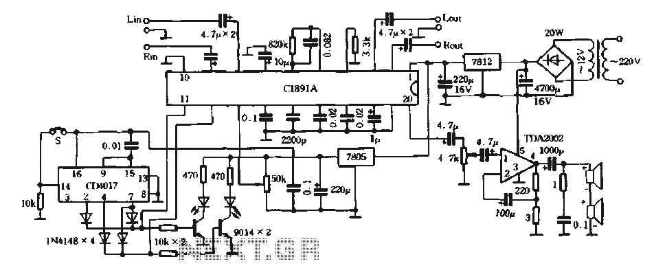
The surround processing section C1891A is a product from Sony Corporation of Japan that features a four-dimensional home theater surround processing circuit. It includes a parent roll phase-shifting circuit and a matrix surround sound amplifier. Additionally, it provides three...
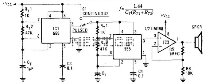
This circuit utilizes two NE555 timer IC devices to generate either pulsed or continuous ultrasonic signals. The values of CT for both pulse rate and ultrasonic frequencies can be calculated accordingly. SPKR refers to a small hi-fi tweeter. The circuit...
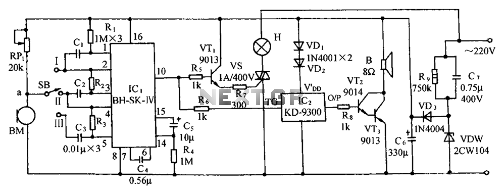
The circuit includes a microphone transducer, voice circuits, an SCR control circuit, a vocal music buck rectifier circuit, and an AC circuit. The BH-SK-IV serves as the core of the device. The described circuit is a complex assembly designed to...
Warning: include(partials/cookie-banner.php): Failed to open stream: Permission denied in /var/www/html/nextgr/view-circuit.php on line 713
Warning: include(): Failed opening 'partials/cookie-banner.php' for inclusion (include_path='.:/usr/share/php') in /var/www/html/nextgr/view-circuit.php on line 713