
Oscillator Design Guide Structure
The Oscillator Design Guide is a comprehensive resource for engineers engaged in oscillator design, particularly in the RF and microwave domains. It provides essential templates and tools to facilitate the design process, allowing users to create and modify oscillator circuits efficiently. The inclusion of various oscillator types—Colpitts, Clapp, Hartley, and their modified versions—ensures that users can select the most suitable configuration for their specific application requirements. The design examples come with detailed measurements and characterization tools that enable users to understand the performance of their designs in both linear and nonlinear domains.
The guide emphasizes the importance of component characterization, providing a library of resonators, devices, and their respective characteristics, which are crucial for accurate design and simulation. The push-button nonlinear measurements serve as a practical starting point for users, allowing them to quickly generate working designs and explore the capabilities of the ADS environment. This flexibility is particularly advantageous for novice users who may require additional guidance.
The oscillator circuits detailed in the guide, such as the Clapp and Hartley oscillators, are designed to operate over a broad frequency range, accommodating various application needs. The use of variable capacitance tuning ports and coupling capacitors enhances tuning capabilities, making these oscillators suitable for voltage-controlled oscillator (VCO) applications. The detailed schematic representations and the ability to adjust component values provide users with the necessary tools to optimize their designs for desired performance specifications.
Overall, the Oscillator Design Guide serves as a vital tool for electronic engineers, streamlining the design process and enhancing understanding of oscillator behavior in complex RF and microwave applications.The Oscillator DesignGuide is integrated into Agilent EEsof`s Advanced Design System environment, working as a smart library and interactive handbook for the creation of useful designs. It allows you to quickly design oscillators, interactively characterize their components, and receive in-depth insight into their operation.
It is easily modifiabl e to user-defined configurations. The first release of this DesignGuide focuses on RF printed circuit boards and microwave oscillations. NoteThis manual assumes that you are familiar with all of the basic ADS program operations. For additional information, refer to the Schematic Capture and Layout manual. The Oscillator DesignGuide contains templates that can be used in the ADS software environment. It consists of generic colpitts, clapp, modified colpitts, modified clapp, and hartley oscillator design examples, and a library of components and component characterization tools.
The push-button nonlinear measurements are recommended as a starting point for both expert and novice users creating large-signal designs. For the expert, these measurements provide an overview of tool capabilities. For the novice user, they provide a working oscillator together with simulations of its typical characteristics of nonlinear designs.
The full set of available large-signal measurements in the Generic Oscillator example are described in Table 2-1. Subsets of these measurements appear in other examples. Refer to the section Additional Examples. Table 2-1 provides descriptions of the available push-button large-signal measurements, as well as the associated filenames for schematics and data displays.
The linear and nonlinear design tools are intended to facilitate you in designing an oscillator from scratch and in gaining insight into an existing oscillator. The full selection of tools is contained in the Generic Oscillator example. Other examples use only those tools that are useful in their particular case. Image of Kurokawa Plots, their justification (describing function method), and definition of large signal S-parameters.
Tools for easy selection of Kurokawa Plots (presented in KurPlot1) The items in the Components and Component Characterization libraries contain a small custom library of resonators and devices, which can help in either modifying an existing oscillator or assembling a new one. They include device DC and S-parameter characteristics, as well as resonator and filter S-parameter and impedance/admittance characteristics.
Table 2-3 through Table 2-5 provide schematic filenames and brief descriptions for each component. Table 2-6 provides schematic filenames and brief descriptions for each component characterization tool. A simple amplifier with capacitive feedback used in frequency pull and push simulations, used above 2GHz (for lower frequencies, see below).
You are encouraged to replace it by your own amplifier and matching circuit. The cClappCore. dsn oscillator operates from 0. 5 to 15GHz using the existing component values in the Clapp oscillator sub-circuit. Resonator tank components Ct and Lt are automatically calculated with approximations referenced to 1GHz and displayed on some display pages. The Ground or Series Resonator port is either connected directly to ground or connected to ground through a series resonator.
The Variable Capacitance Tuning Port is used for VCO design by coupling a varactor diode across the tank capacitor Ct. Coupling is accomplished by capacitor Ccpl. Larger values of Ccpl yield tighter coupling and wider tuning range for a given amount of tuning capacitance variation.
The OscPort1 and OscPort2 ports are either connected directly together or connected through a series resonator. You can connect the OscPort test probe between these two ports for harmonic balance oscillator simulations.
The Output Port is used for oscillator signal output. The variable Ctune sets the oscillator at the desired oscillation frequency when the capacitance across the Variable Capacitance Tuning Port is equal to the Ctune set value. Figure 2-2 is an example of the Clapp Oscillator subcircuit. Increase capacitors C1 and C2 for lower frequency oscillator circuits. Adjust resonator frequency offset (currently 390E6) to recenter oscillator frequency. Figure 2-3 shows the cHartleyCore. dsn oscillator core schematic symbol. This oscillator operates from 1 to 1000MHz using the existing component values in the Hartley oscillator sub-circuit.
The resonator tank component Ct is scaled from 500MHz with an approximation and displayed on some display pages. You can connect the Ground or Series Resonator to the port directly to ground, or it can be connected to ground through a series resonator.
The Variable Capacitance Tuning Port is used for VCO design by coupling a varactor diode across the tank capacitor Ct. Coupling is accomplished by capacitor Ccpl. Larger values of Ccpl yield tighter coupling and wider tuning range for a given amount of tuning capacitance variation.
The OscPort1 and OscPort2 ports are either connected directly together or connected through a series resonator. For harmonic balance oscillator simulations, connect the OscPort test probe between these two ports. The Output Port is used for oscillator signal output. The variable Ctune sets the oscillator at the desired oscillation frequency when the capacitance across the Variable Capacitance Tuning Port is equal to the Ctune set value.
Figure 2-4 shows the Hartley Oscillator subcircuit. Increase inductors L1 and L2 for lower frequency oscillator circuits. Adjust resonator capacitor Ct reference value (currently 21. 3pF) to recenter oscillator frequency. Figure 2-5 shows the cModifiedClappCore. dsn oscillator core schematic symbol. The cModifiedClappCore. dsn oscillator operates from 0. 7 to 7. 2GHz using the existing component values in the Modified Clapp oscillator sub-circuit. Resonator tank components Ct and Lt are automatically calculated with approximations referenced to 1GHz and displayed on some display pages. The Ground or Series Resonator port can be connected directly to ground or connected to ground through a series resonator.
The Variable Capacitance Tuning Port is used for VCO design by coupling a varactor diode across the tank capacitor Ct. Coupling is accomplished by capacitor Ccpl. Larger values of Ccpl yield tighter coupling and wider tuning range for a given amount of tuning capacitance variation.
The OscPort1 and OscPort2 ports are either connected directly together or connected through a series resonator. You can connect the OscPort test probe between these two ports for harmonic balance oscillator simulations.
The Output Port is used for oscillator signal output. Variable Ctune sets the oscillator at the desired oscillation frequency when the capacitance across the Variable Ca as well. 🔗 External reference
Related Circuits

This circuit is designed as a pocket-sized, high-performance audio oscillator. It can operate using a battery-powered version, which is feasible at a very low cost by utilizing a single quad op-amp to provide the entire active circuitry. The design...
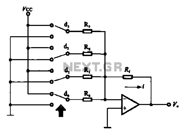
An A/D converter circuit can be represented by a simplified schematic, which illustrates a parallel type A/D converter. The term "median" refers to the number of bits in the digital signal output. The figure displays four A/D converters utilizing...
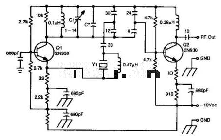
This oscillator circuit utilizes a 5th overtone crystal operating within the 85 to 106 MHz frequency range. The component Y1 represents the crystal. The circuit was initially designed for frequency control in a microwave oscillator. The oscillator circuit leveraging a...
The control on the PCB is set at specific positions with the following capacitance values and their corresponding measured frequencies: For a capacitance of 100 pF, the frequencies are 6 kHz, 12.05 kHz, and 26 kHz. For 470 pF,...
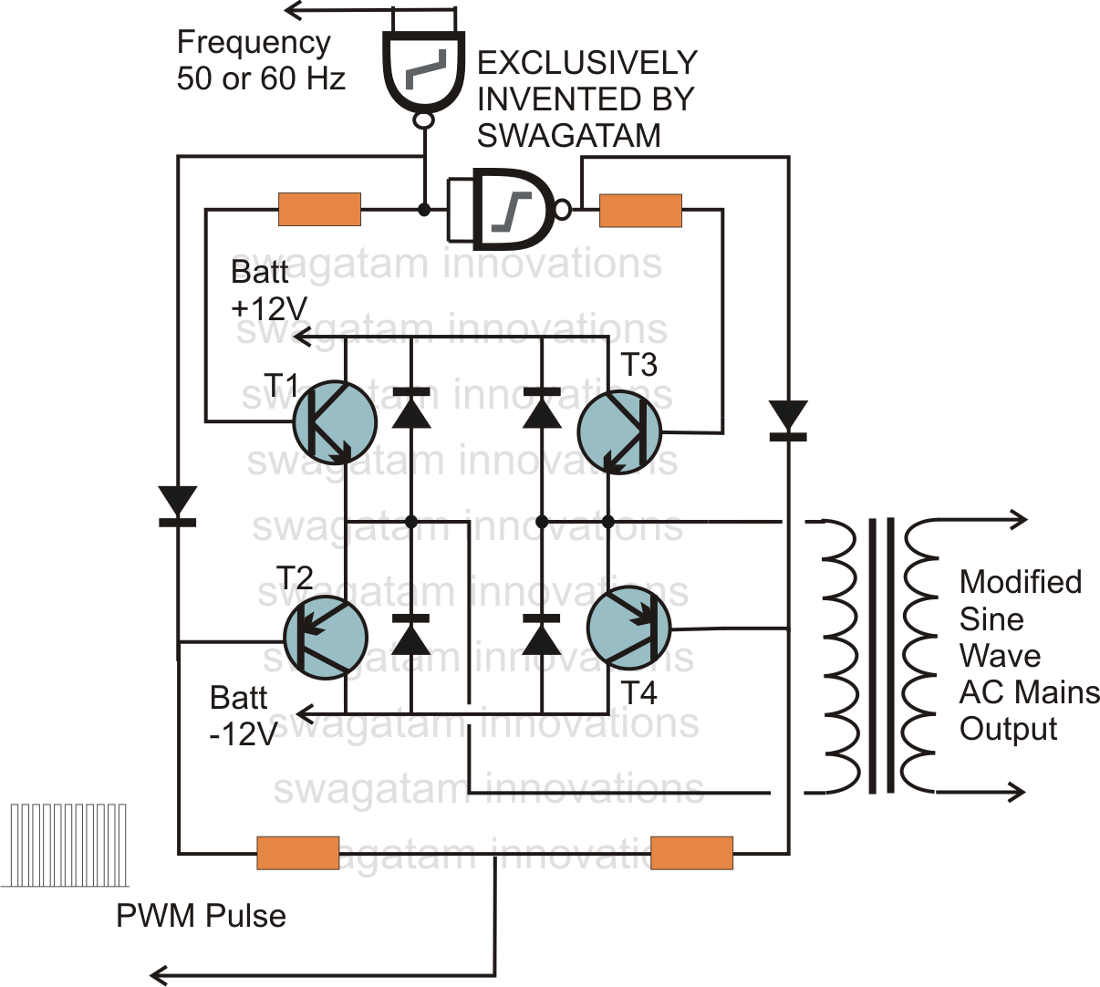
In electronics, an H-bridge circuit refers to a configuration consisting of four individual switching devices, such as transistors or MOSFETs, which can be controlled by external discrete signals from the respective stages of the control circuit. During operation, the...
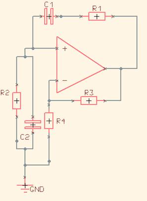
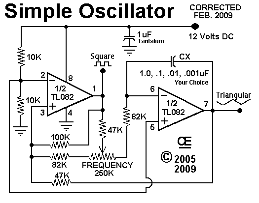
One of the simplest sine wave oscillators is the Wien Bridge Oscillator. Any circuit requires two conditions to oscillate. Tracing the path from the input, through the feedback network, and back to the input, there must be an overall...