
oscillator Is this a suitable sine wave osc? how would I control the frequency
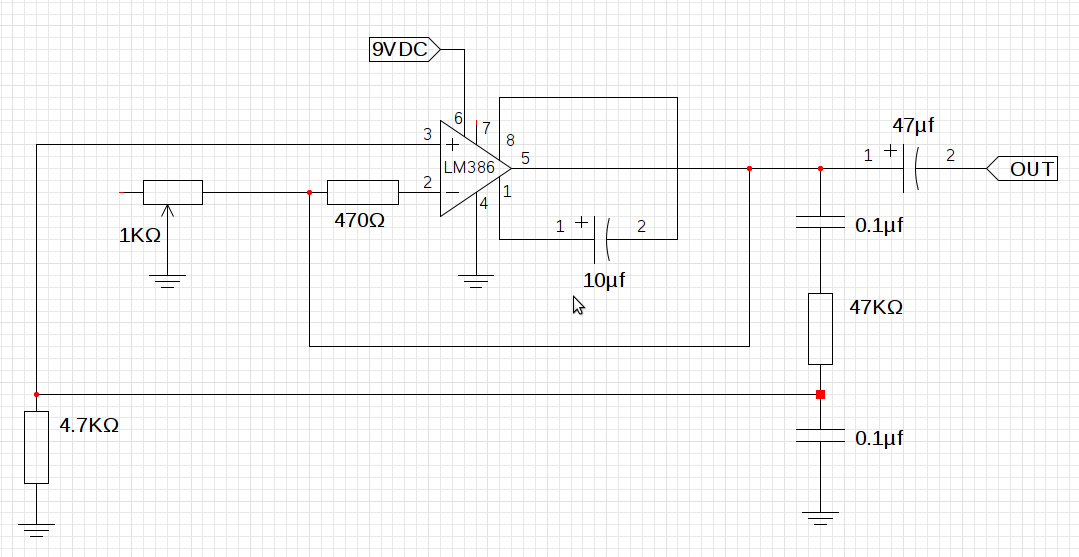
The LM386n-1 is a low-voltage audio power amplifier designed for use in battery-powered applications. It typically operates with a power supply range of 4 to 12 volts and is capable of delivering up to 1 watt of output power into an 8-ohm load. This IC is suitable for applications that require a compact design due to its small footprint and minimal external components.
To control the frequency of the output signal, it is essential to focus on the timing components used in the circuit. The frequency can typically be adjusted by changing the values of capacitors and resistors in the feedback network of the amplifier. In many configurations, the frequency is determined by the RC time constant, which is influenced by both resistance and capacitance values.
If the goal is to modify the pitch, it may be necessary to experiment with the capacitors in the feedback loop. For instance, increasing the capacitance will lower the frequency, while decreasing it will raise the frequency. Additionally, the resistors in the feedback path can also be adjusted; however, their interdependence suggests that a systematic approach to changing one component at a time will yield the best results.
In terms of implementing an Automatic Gain Control (AGC), various options are available. One common approach is to use a diode-based AGC circuit, which can help maintain a consistent output level by adjusting the gain based on the input signal amplitude. Another option could be to integrate a dedicated AGC IC that automatically adjusts the gain based on the detected signal level.
Ultimately, the selection of components for the AGC will depend on the specific requirements of the application, including the desired response time and the dynamic range of the input signal. Careful consideration of these factors will enhance the overall performance of the final circuit design.As I`m working from a single power supply and I`m trying to keep the design small, I`ve been using the LM386n-1 IC. Also, how would you suggest I control the frequency, which component value should be changed to achieve this - I`ve tried messing with all the resistors to change the pitch, but theyall seem to be interdependent.
And this is what my implementation looks like, I don`t have a suitable incandescent bulb so I`ve just replaced it with a 1K © pot. I`m still not sure what I`ll use in the final circuit as AGC, suggestions are welcome. 🔗 External reference
Related Circuits
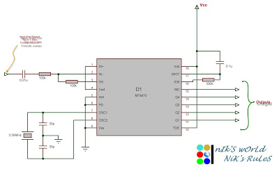
Connect the serial cable to the serial port. If using a USB to TTL, RS232, or serial converter, plug it into the USB port. Next, short the Tx pin to the Rx pin or the TxD pin to the...
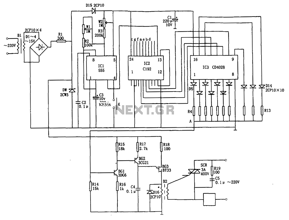
The automatic conversion circuit for wind speed control is depicted in Figure 10. This circuit consists of a clock signal generator (IC1), a counter (IC2), a decoder (IC3), a synchronous phase shifting circuit (BG1, BG2, BG3), a thyristor control...
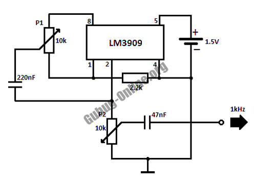
This circuit design for a high-frequency waveform generator is highly beneficial for electronic experiments and designs. The circuit generates sine wave oscillations, but it can also be modified to produce triangle or square wave functions. The high-frequency waveform generator circuit...
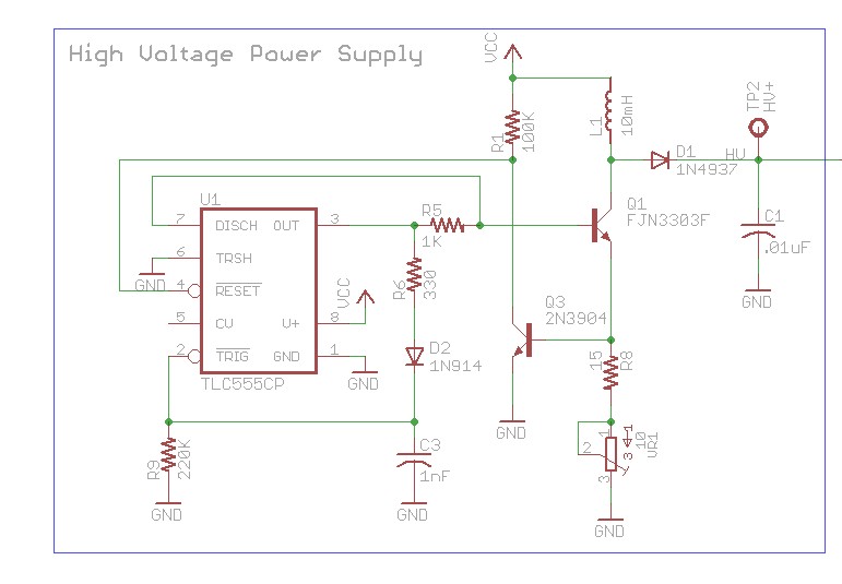
The design involves using a 555 timer as an oscillator in the high voltage power supply section. There is a query regarding the possibility of altering the design to utilize an output from a microcontroller to generate an oscillating...
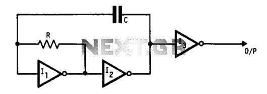
This oscillator utilizes standard inverters, one resistor, and one capacitor, and it does not have a minimum operating frequency. The resistor (R) and capacitor (C) must be selected to ensure that the currents flowing into the gates remain below...
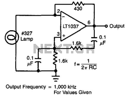
In this circuit, the Wien bridge network provides phase shift, and the lamp regulates the amplitude of the oscillations. The smooth, limiting nature of the lamp's operation, in combination with its simplicity, yields good results. Harmonic distortion is below...
Warning: include(partials/cookie-banner.php): Failed to open stream: Permission denied in /var/www/html/nextgr/view-circuit.php on line 713
Warning: include(): Failed opening 'partials/cookie-banner.php' for inclusion (include_path='.:/usr/share/php') in /var/www/html/nextgr/view-circuit.php on line 713