
Oscilloscope-preamplifier
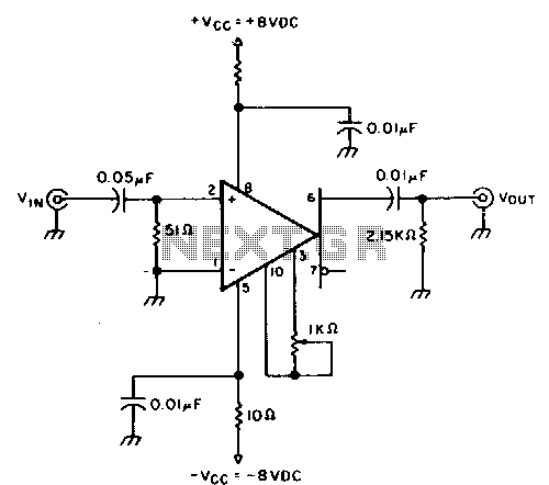
This circuit provides approximately 20 dB of voltage gain with a frequency range from 0.5 to 50 MHz. The low-frequency response of this circuit can be extended by increasing the value of the 0.05 µF capacitor or by removing the capacitor altogether. This circuit delivers a notably low level of input noise, measured at around 20 µV across a bandwidth range of 15 MHz. Calibration of the gain can be performed by adjusting the gain potentiometer connected between pins 3 and 10, followed by fine-tuning the 1 kΩ trimmer potentiometer to achieve an exact voltage gain of 10, which helps maintain the -Vee to -Vosc scale factor of the oscilloscope.
This circuit operates as a voltage amplifier, designed to provide a stable gain while minimizing noise interference. The specified gain of 20 dB indicates that the output voltage is 10 times the input voltage, making it suitable for applications requiring signal amplification within the specified frequency range. The ability to adjust the low-frequency response by modifying the capacitor value allows for flexibility in various applications, particularly in audio or RF signal processing.
The input noise level of approximately 20 µV is particularly advantageous in precision measurement applications, where maintaining signal integrity is crucial. The circuit's design ensures that the noise figure remains low, enhancing the overall performance in sensitive environments.
The calibration process is essential for ensuring accurate gain settings. The gain potentiometer, strategically placed between pins 3 and 10, allows for coarse adjustments, while the 1 kΩ trimmer potentiometer enables fine-tuning to achieve the desired gain of 10. This calibration is critical for maintaining the oscilloscope's scale factor, ensuring that the measurements reflect the true characteristics of the signal being analyzed.
In summary, this circuit represents a robust solution for voltage amplification with adjustable gain and low noise characteristics, making it suitable for a variety of electronic applications requiring precision and reliability.This circuit provides about 20 dB voltage gain with a frequency range from 0.5 to 50 MHz. You can extend tbe low-frequency response of this circuit by increasing tbe value of the 0.05-ILF capacitor- or try removing tbe capacitor. This circuit delivers a particularly small level of input noise, measured at approximately 20 p.V over a bandwidth range of 15 MHz.
Calibrate the gain by adjusting tbe gain potentiometer connected between pins 3 and 10, tben adjust the 1-KO trimmer potentiometer for an exact voltage gain of 10; this helps preserve the -vee· -svoc scale factor of the oscilloscope. 🔗 External reference