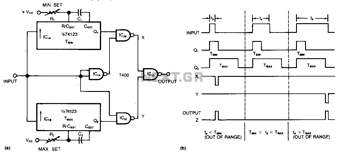
Out-of-bounds-pulse-width-detector

This circuit requires only two integrated circuits (ICs) to monitor a train of positive pulses and produces a single positive output pulse for each input pulse that falls outside specified duration limits. The minimum and maximum limits can be defined by adjusting the trimming potentiometers, R1 and R2. The acceptable pulse width can be set from approximately 50 ns to 10 µs, utilizing a 74123 monostable multivibrator. The leading edge of an input pulse triggers one-shots IC1A and IC1B, as illustrated in the timing diagram. Each NAND gate output remains high unless one or both inputs are low, which means outputs X and Y are high unless the circuit detects an out-of-range pulse. IC2D then gates a negative pulse from either IC2B or IC2C to generate the circuit's positive output pulse.
This circuit design efficiently utilizes two ICs to monitor pulse widths and generate a corresponding output pulse, ensuring that only pulses within a specified range are processed. The 74123 monostable multivibrator serves as a crucial component, allowing for precise control over the pulse width by adjusting the connected trimming potentiometers, R1 and R2. The selected values for these resistors determine the minimum and maximum pulse width thresholds, enabling customization for various applications.
When an input pulse is detected, the leading edge triggers the one-shot configurations of IC1A and IC1B, which are responsible for responding to the timing characteristics of the incoming pulses. The outputs of these one-shots are then fed into the NAND gates, which function to maintain a high output state unless a low input condition is detected. This ensures that the circuit can effectively identify pulses that exceed the predefined duration limits.
If either of the outputs from the NAND gates (X or Y) goes low, indicating an out-of-range pulse, IC2D is activated. This IC gates a negative pulse from either IC2B or IC2C, resulting in the generation of a positive output pulse. This mechanism guarantees that only pulses that meet the specified criteria are translated into output signals, thereby enhancing the reliability and accuracy of pulse monitoring in various electronic systems. The overall design is compact and efficient, making it suitable for applications that require precise pulse width detection and response.Requiring only two ICs to monitor a train of positive pulses, this circuit produces a single positive output pulse for each input pulse whose duration is either too long or too short. You specify the minimum and maximum limits by adjusting the trimming potentiometers, R1 aod R2. You cao set the value of the acceptable pulse width from approximately 50 ns to 10 f-!S, for a 74123 monostable multivibrator.
The leading edge of ao input pulse triggers one shots IClA and IClB as you cao see from the timing diagram. Each NAND-gate output is high unless either or both inputs are low, so outputs X aod Y are high unless the circuit encounters an out-of-range pulse. IC2D then gates a negative pulse from IC2B or ICZC to produce the circuit"s positive output pulse.