
Over-under-voltage-monitor
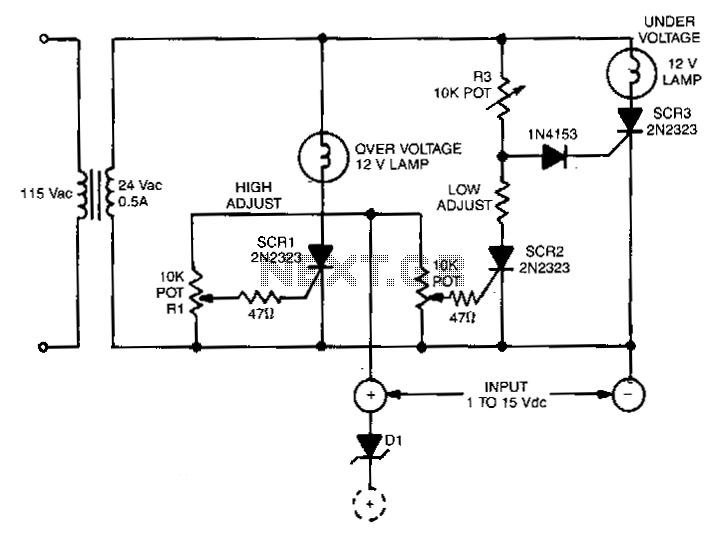
This circuit is capable of monitoring any voltage potential ranging from 1 to 15 V. It features two lamps that indicate any undesirable voltage variations. The voltage differential between the lamp turning on and turning off is approximately 0.2 V at any setting. The high and low set points are independent of one another. The silicon-controlled rectifiers (SCRs) utilized in this circuit should be of the sensitive gate type. The resistor R3 must be determined through experimentation for the specific series of SCRs employed. This adjustment is made by setting R3 to the point where the undervoltage lamp activates when there is no signal present at the gate of SCR2. To monitor any 15-V segment, the zener diode D1 should be connected in series with the positive input lead. Consequently, the low set-point voltage will be the zener voltage plus 0.8 V.
The described circuit employs a monitoring system that effectively tracks voltage levels from 1 to 15 V, utilizing visual indicators in the form of lamps to signal any deviations from desired voltage thresholds. The implementation of two lamps allows for a clear distinction between high and low voltage conditions, providing immediate visual feedback when the monitored voltage strays from predefined limits.
The use of sensitive gate SCRs is crucial in this design, as they ensure reliable operation with minimal gate current requirements. The experimental determination of resistor R3 is an important step in the calibration process, as it directly influences the sensitivity and responsiveness of the undervoltage detection mechanism. By adjusting R3, the circuit can be fine-tuned to ensure that the undervoltage lamp activates precisely at the intended threshold, thereby enhancing the accuracy of the monitoring system.
The integration of a zener diode, D1, allows for the monitoring of specific voltage segments within the overall range. By placing the zener diode in series with the positive input lead, the circuit can effectively establish a low set-point voltage that accounts for the zener voltage and an additional 0.8 V. This configuration enables the circuit to adapt to different voltage segments while maintaining the integrity of the monitoring function.
Overall, this circuit design provides a robust solution for voltage monitoring applications, combining sensitivity, adaptability, and clear visual indicators to ensure effective oversight of voltage levels across a specified range.Any potential from 1 to 15 V can be monitored with this circuit. Two lamps alert any undesirable variation. The voltage differential from lamp tum-on to tum-off is about 0.2 Vat any setting. High and low set points are independent of each other. The SCRs used in the circuit should be the sensitive gate type. R3 must be experimentally determined for the particular series of SCRs used. This is done by adjusting R3 to the point where the undervoltage lamp turns on when no signal is present at the SCR2 gate. Any 15-V segment can be monitored by putting the zener diode, D1, in series with the positive input lead.
The low set-point voltage will then be the zener voltage plus 0.8 V. 🔗 External reference