
Overtone crystal oscillator
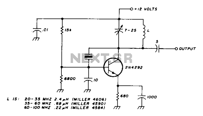
The oscillator circuit is specifically tailored to utilize overtone crystals, which are designed to resonate at higher frequencies, typically in the third and fifth overtone modes. These modes allow for efficient frequency multiplication, enabling the oscillator to generate signals within the specified frequency range of 20-100 MHz.
The core component of the oscillator is the overtone crystal, which is characterized by its high Q factor, providing stability and low phase noise. The tuned circuit, which consists of inductors and capacitors, plays a crucial role in determining the operating frequency. By adjusting the values of these reactive components, the circuit can be finely tuned to achieve the desired frequency output.
In designing the oscillator, attention must be given to the load capacitance and the series resistance of the crystal, as these factors influence the performance and efficiency of the oscillator. Additionally, the circuit may incorporate feedback mechanisms to enhance stability and minimize drift over time.
Power supply considerations are also critical, as the oscillator must operate within specified voltage and current limits to ensure reliable performance. The output stage of the oscillator can be designed to drive various loads, depending on the application, whether it be for RF transmission, signal generation, or clocking applications in digital circuits.
Overall, this oscillator design is suitable for applications requiring precise frequency generation in the specified MHz range, leveraging the properties of overtone crystals to achieve high performance and reliability.This oscillator is designed for overtone crystals in the 20-100 MHz range operating in the third and fifth mode. Operating frequency is determined by the tuned circuit. 🔗 External reference
Related Circuits
A 2N366 is configured as an audio feedback oscillator using an audio transformer. Adjust R1 for proper operation and the desired audio note. The circuit utilizes a 2N366 transistor, which is a general-purpose NPN transistor, serving as the primary active...
An op-amp based Colpitts oscillator in Multisim displays a "timestep too small" error when the run button is pressed. Despite extensive research and attempts to resolve the issue, the error persists. The design features a C-L-C pi circuit that...
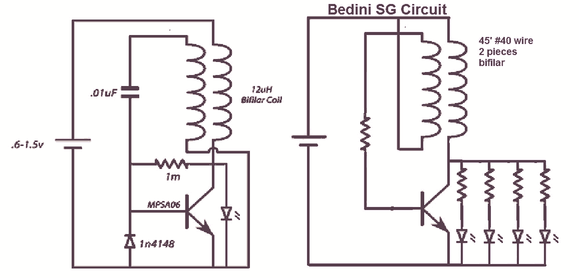
It would be beneficial to obtain schematics of the Joule Thief and Bedini oscillator circuit connections. This is an area that has not been previously explored. The schematic on the left was sourced from the Energetic Forum, while the...
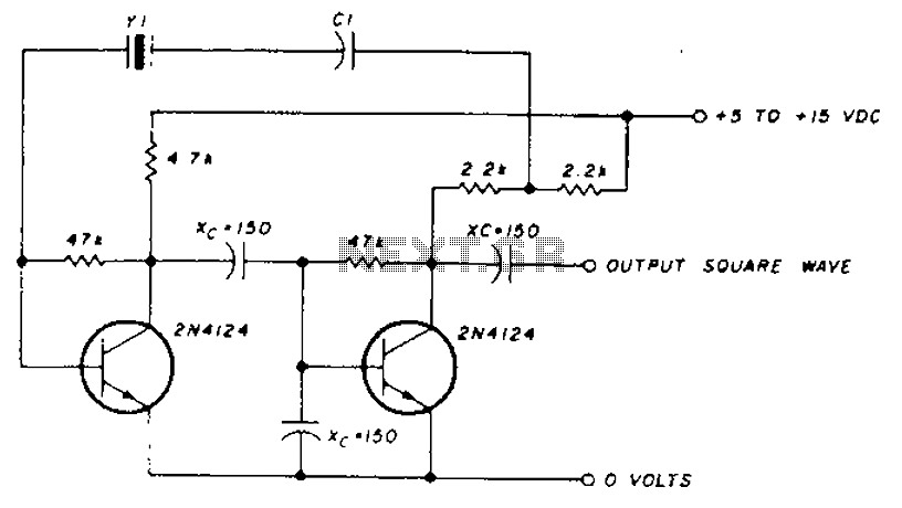
A transistor in series with capacitor C1 can be utilized to adjust the oscillator output frequency. The frequency may vary with changes in capacitance ranging from 20 pF to 0.01 µF, or as determined by the tuning capacitor. The...
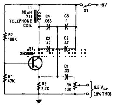
An 88 mH surplus telephone toroidal coil is utilized in a 1 kHz oscillator. It can provide up to 8 V peak-to-peak into a high-impedance load. The total harmonic distortion (THD) is 0.9%. The circuit employs an 88 mH toroidal...
BFO is a simple device which helps us to listen SSB and CW transmissions. Reception of SSB and CW signals requires a product detector or BFO (Beat Frequency Oscillator) to reinsert the missing carrier. This circuit is very simple...
Warning: include(partials/cookie-banner.php): Failed to open stream: Permission denied in /var/www/html/nextgr/view-circuit.php on line 713
Warning: include(): Failed opening 'partials/cookie-banner.php' for inclusion (include_path='.:/usr/share/php') in /var/www/html/nextgr/view-circuit.php on line 713