
park aid schematics
IC1 functions as a key component in generating a consistent pulse signal that drives the infrared LED (D1). The 0.8 ms pulse duration at a frequency of 120 Hz ensures that the LED emits infrared light intermittently, allowing for effective distance measurement when the light is reflected back to the photodiode (D2). The arrangement of D1 and D2 is critical; they must be precisely aligned to maximize the detection of the reflected infrared signal.
The amplification stage, which includes IC2A, enhances the weak signal received by D2, ensuring that even minor reflections can be detected. The peak detection circuit formed by D4 and C4 is essential for converting the amplified signal into a usable DC voltage that correlates with the distance of the reflecting object. The compensatory action of D3 with resistors R5 and R6 is vital for maintaining accuracy by accounting for any voltage drops that may occur across D4, ensuring that the voltage readings remain reliable.
The voltage comparators play a crucial role in the circuit's functionality, as they compare the processed voltage with predetermined reference levels set by the voltage divider network (R7-R10). This comparison determines when to activate or deactivate the signaling LEDs, allowing for a visual indication of the distance measured. The use of a regulated power supply via IC3 is necessary to prevent fluctuations that could affect the reference voltages and, consequently, the performance of the comparators.
For optimal performance, the infrared photodiode D2 should be selected carefully to include a sunlight filter, ensuring it only responds to the infrared light emitted by D1. The physical arrangement of the components is also significant; housing the circuitry close to the LEDs minimizes interference and enhances signal integrity. The signaling LEDs, which provide visual feedback to the user, should be positioned at a height that ensures they are easily visible to a driver, facilitating effective operation of the system. The tuning process for D1 and D2 is straightforward and involves adjusting their distance until the desired sensitivity is achieved, with the typical effective range being between 1.5 and 3 cm.IC1 forms an oscillator driving the infra-red LED by means of 0. 8mSec. pulses at 120Hz frequency and about 300mA peak current. D1 & D2 are placed facing the car on the same line, a couple of centimeters apart, on a short breadboard strip fastened to the wall. D2 picks-up the infra-red beam generated by D1 and reflected by the surface placed in fro nt of it. The signal is amplified by IC2A and peak detected by D4 & C4. Diode D3, with R5 & R6, compensates for the forward diode drop of D4. A DC voltage proportional to the distance of the reflecting object and D1 & D2 feeds the inverting inputs of three voltage comparators. These comparators switch on and off the LEDs, referring to voltages at their non-inverting inputs set by the voltage divider resistor chain R7-R10.
Power supply must be regulated (hence the use of IC3) for precise reference voltages. The circuit can be fed by a commercial wall plug-in adapter, having a DC output voltage in the range 12-24V. The infra-red Photo Diode D2, should be of the type incorporating an optical sunlight filter: these components appear in black plastic cases.
Some of them resemble TO92 transistors: in this case, please note that the sensitive surface is the curved, not the flat one. It is wiser to place all the circuitry near the infra-red LEDs in a small box. The 3 signaling LEDs can be placed far from the main box at an height making them well visible by the car driver.
The best setup is obtained bringing D2 nearer to D1 (without a reflecting object) until D5 illuminates; then moving it a bit until D5 is clearly off. Usually D1-D2 optimum distance lies in the range 1. 5-3 cm. 🔗 External reference
Related Circuits
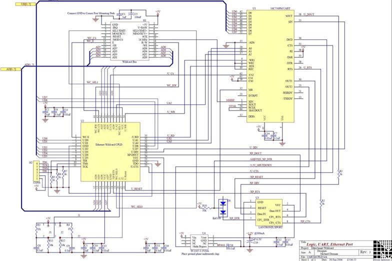
The EtherSmart Wildcard is based on the Lantronix Xport Ethernet device server, which is integrated into an RJ-45 connector housing. The Xport communicates data through a serial UART-USART interface, while the Wildcard bus operates as a parallel interface. A...
This timer is designed to automatically switch off a portable radio after a set period, allowing users to relax without worrying about battery drain. Resistor R1 and capacitor C1 create a long time constant. When switch P2 is momentarily...
An RC car has been developed that can autonomously identify a parking space and execute parallel parking maneuvers. The car navigates along a street using a distance sensor to locate potential parking spaces on its right. Upon identifying a...
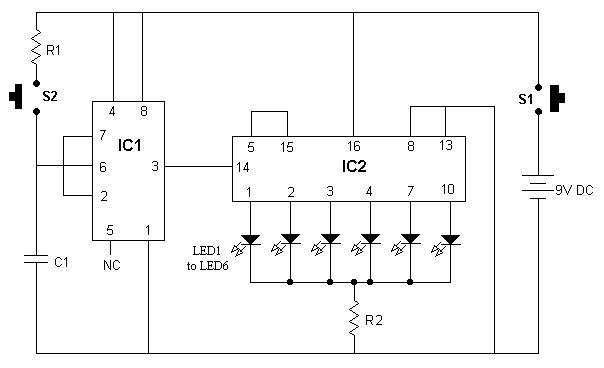
It is advisable to enclose this circuit in a box and label each LED with numbers from 1 to 6. When switch S1 is momentarily pressed, one of the six LEDs will illuminate, with the number corresponding to the...
This circuit has an automatic switch on for the rear gear, a LED bar graph display, and an audible beep on the last LED. It features a "good old" design style with no microcontrollers. Based on an ultrasonic amplifier...
This page introduces an engaging project designed by Toon Beerten, titled "DIY LED Mood Lamp." This project serves as an intriguing addition to any room, guaranteed to impress viewers. The lamp features a color-fading effect that enhances its visual...