
passive aircraft receiver

The Passive Aircraft Receiver circuit operates primarily as a simple yet effective AM receiver, leveraging the principles of crystal radio technology. The absence of active RF components minimizes the risk of interference with aircraft communication systems, making it compliant with stringent aviation regulations. The use of a Schottky detector diode, such as the 1N5711, is crucial for its efficiency in demodulating AM signals, as Schottky diodes exhibit low forward voltage drop and fast switching capabilities, which are advantageous in radio frequency applications.
The tuning mechanism is facilitated by a variable capacitor, which adjusts the resonant frequency of the LC circuit formed with the inductor. The choice of inductor, specified at 0.15 µH, is vital for ensuring the receiver can adequately tune into the desired frequency range, particularly the AM aircraft bands. The inductor's physical construction can vary, with options ranging from molded chokes to hand-wound coils, allowing for experimentation to optimize performance.
The circuit design includes a dual op-amp (LM358) for signal amplification, ensuring that the audio output is sufficiently strong for listening through a speaker or earphone. The low current draw of the LM358 contributes to the overall efficiency of the receiver, providing extended operational periods on a single battery charge.
Antenna design is also a critical factor in the performance of the receiver. The length and type of antenna directly influence the receiver's sensitivity and selectivity. A shorter antenna is preferred for proximity to the transmitter, while longer antennas can improve reception range but may compromise selectivity. Adjustments to the capacitor values in relation to antenna length can help fine-tune the receiver's performance, allowing for optimal signal reception under varying conditions.
Overall, the Passive Aircraft Receiver represents a practical solution for enthusiasts interested in monitoring AM aircraft communications within regulatory constraints, providing a hands-on opportunity to explore radio frequency principles while ensuring compliance with aviation safety standards.The Passive Aircraft Receiver is basically an amplified "crystal radio" designed to receive nearby AM aircraft transmissions. The "passive" design uses no oscillators or other RF circuitry capable of interfering with aircraft communications so it should be fine inside the cabin of the aircraft.
Nevertheless, check the regulations before using this receiver on a commercial airliner. New security regulations probably prohibit this device on commercial flights. Do not expect to hear two-way aircraft transmissions with this receiver! It is a short-range receiver only. The detector diode is a 1N5711, HP2835 or similar Schottky detector diode. The 10 megohm resistors provide a small diode bias current for better detector efficiency. The tuning capacitor may be any small variable with a range from about 5 pF to about 15 or 20 pF. The 0. 15 uH inductor may be a molded choke or a few turns wound with a small diameter. Experiment with the coil to get the desired tuning range. The aircraft frequencies are directly above the FM band so a proper inductor will tune FM stations with the capacitor set near maximum capacity. (The FM stations will sound distorted since they are being slope detected. ) Other capacitor and inductor combinations may be selected to tune other bands if desired. (Try the CB band at 27 MHz. ) The LM358 dual op-amp draws under 1 ma so the battery life is quite long. A speaker amplifier may be added to drive a speaker or low-z earphone. The antenna can be a couple of inches if the receiver is near the transmitter or a couple of feet for maximum range.
The selectivity is reduce as the antenna length is increased so best performance is achieved with the shortest acceptable antenna. Try increasing the 1. 8 pF capacitor value when using very short antennas and decreasing it for long antennas. The receiver could be built into a small plastic box with a short antenna inside. 🔗 External reference
Related Circuits
The induction receiver described is highly sensitive and versatile, suitable for various applications including tracing wiring behind walls, receiving audio from an induction transmitter, detecting lightning and other electrical discharges, and monitoring devices that produce an audio magnetic field,...
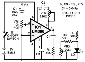
Laser communication system circuit diagram. The circuit module consists of a transmitter and a receiver that utilize the IC LM386. It is powered by a 9V battery. The laser communication system is designed to facilitate wireless data transmission using modulated...
This article discusses simple FM direct conversion radio receivers utilizing a phase-locked loop (PLL). These receivers operate by locking the local oscillator frequency to the input signal. All FM receivers are based on a circuit that combines an oscillator...
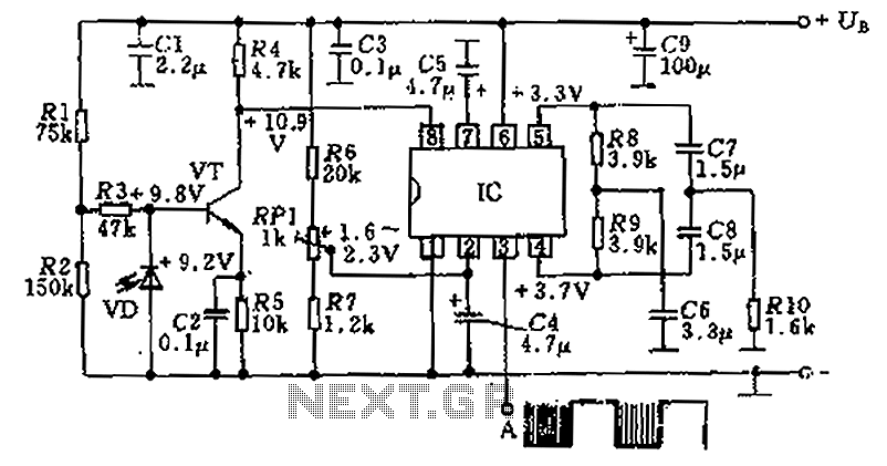
The circuit utilizes an integrated amplifier, resulting in a simple and compact design. The TDA4050 IC is employed, where a weak signal is received by the infrared photodiode (VD) and first passes through a transistor amplifier. The circuit is...
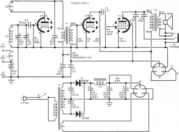
RF Cafe visitor David M. requested the scanning and posting of an article from the January 1963 edition of Popular Electronics, authored by Philip Hatfield from the Receiving Tube Department of General Electric. The article describes a straightforward design...
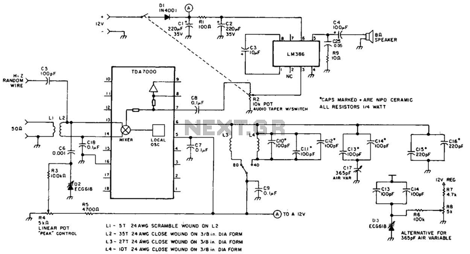
This direct-conversion receiver utilizes a TDA7000 integrated circuit (IC) and incorporates an LM386 audio amplifier. The TDA7000 serves as the mixer and local oscillator (L.O.) section. The frequency control can be achieved using either an air variable capacitor or...