
PC Controlled Voltage or Current Source
The described project encompasses a circuit designed for charging and cycling Nickel-Cadmium (NiCad) batteries, with the added capability of providing a variable output voltage of up to +30V and a current of +/- 2.5 Amps. The circuit architecture is likely to include a voltage regulator, operational amplifiers, and possibly a microcontroller to manage the charging cycles and monitor battery conditions.
The charging mechanism typically employs a constant current/constant voltage (CC/CV) approach, which is essential for the safe and efficient charging of NiCad batteries. The voltage regulator would be responsible for maintaining the output voltage within the specified range, ensuring that the batteries are charged without exceeding their voltage limits, which could lead to damage or reduced lifespan.
In terms of the current handling capabilities, the circuit must incorporate appropriate power components, such as MOSFETs or BJTs, that can handle the specified current ratings. Current sensing resistors may be utilized in conjunction with operational amplifiers to provide feedback for current regulation, allowing for precise control over the charging process.
For experimental applications, the circuit could feature adjustable resistors or digital potentiometers, enabling the user to modify output parameters easily. Additionally, safety features such as thermal cutoffs, fuses, or circuit breakers are recommended to protect both the circuit and the batteries from overcurrent conditions.
Overall, while the project offers a versatile platform for experimentation with battery charging and cycling, it is essential to consider the limitations and potential shortcomings inherent in a custom-designed circuit compared to commercially available solutions. Proper attention to circuit design, component selection, and safety measures will enhance performance and reliability in practical applications.This project was begun as a means to charge and cycle NiCad batteries but has become a versatile tool for experiments requiring either a controlled voltage up to +30V and/or a current of +/- 2.5 Amps. If all you want to do is charge and recycle NiCad batteries, then, with hindsight, I`d advise you to buy one of the commerical units available.
The circuit I will describe will do the job but it is experimental and has many short comings. 🔗 External reference
Related Circuits
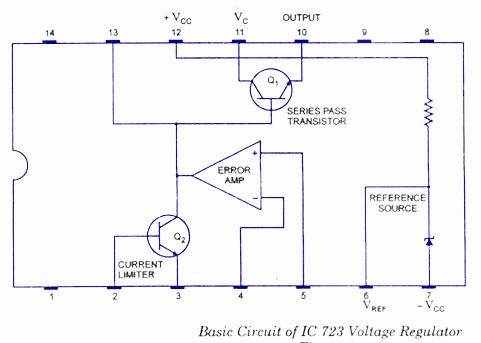
The working and block diagram of the IC 723 Voltage Regulator is provided along with the circuit diagram and applications. The IC 723 is a voltage regulator integrated circuit that is widely used for providing a stable output voltage. It...
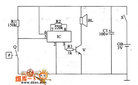
This touch-controlled musical bell circuit generates a musical tone whenever someone touches the designated touch point (TP). The circuit operates using two AA batteries and produces sufficient sound output. It utilizes the UM3481 integrated circuit, which is commonly employed...
The OPB350 series liquid sensor is designed to operate with clear tubes of various outer diameters: 1/16 inch (1.6 mm), 1/8 inch (3.2 mm), 3/16 inch (4.8 mm), and 1/4 inch (6.3 mm). When integrated with output reference circuitry,...
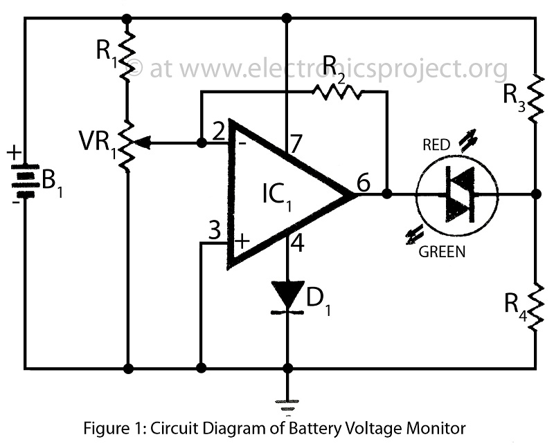
Battery voltage monitor is utilized to indicate the voltage level of a 12-volt battery circuit, specifically in a verified electronics project circuit. The battery voltage monitor circuit is designed to provide a visual representation of the voltage level of a 12-volt...
The TL494 serves as the core component for a PWM driver and protection circuit operating at a frequency of 50 kHz. The output voltage of 115V is stepped down and isolated before being sent to the TL494 error amplifier...
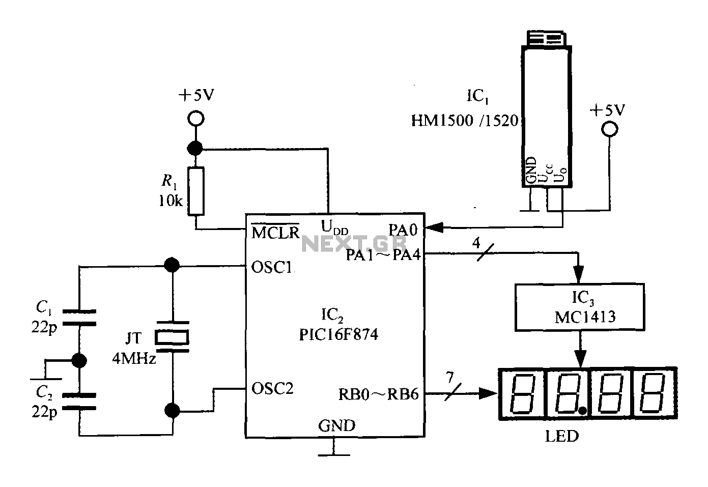
An intelligent humidity meter circuit utilizing the HM1500/1520 humidity sensor and a microcontroller configuration. The circuit operates on a +5V power supply and incorporates four common cathode LED digital displays. It employs three integrated circuits: IC1 is the HM1500/1520...