
pc frs radio control

This project focuses on establishing a communication link between a personal computer (PC) and a small Family Radio Service (FRS) radio using an RS-232 serial interface. The RS-232 standard is widely utilized for serial communication and is compatible with many devices, making it an ideal choice for this application.
To implement this connection, the following components are typically required: an FRS radio with an appropriate interface port, a PC equipped with a serial port or USB-to-serial adapter, and an RS-232 cable. The RS-232 cable must be wired correctly to ensure proper communication. The pinout configuration for the FRS radio must be verified to match the RS-232 standard, which usually includes connections for transmit (TX), receive (RX), ground (GND), and potentially other control signals.
The software component of this project may involve terminal emulation programs that can send and receive data through the RS-232 interface. This software allows the user to interact with the FRS radio, enabling functionalities such as changing channels, sending messages, or configuring settings remotely from the PC.
It is important to consider voltage levels when interfacing the PC and the FRS radio, as RS-232 signals typically operate at higher voltage levels (±12V) compared to the logic levels used in many modern electronic devices. Level shifting circuits may be necessary to ensure compatibility and protect both devices from potential damage.
Overall, this project serves as a practical example of interfacing different communication technologies, showcasing the versatility of RS-232 in connecting legacy devices with modern computing platforms.tutorials reviews software airsoft Introduction This project illustrates how to connect a PC to a small FRS radio via a simple RS-232 interface. There are several reasons that you may want to.. 🔗 External reference
Related Circuits
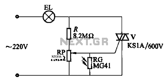
An automatic light control circuit is designed to illuminate a lamp when it is dark and to turn off the light at daybreak. The circuit, as shown in Figure 2-86, employs bidirectional thyristor tubes and features a straightforward design....
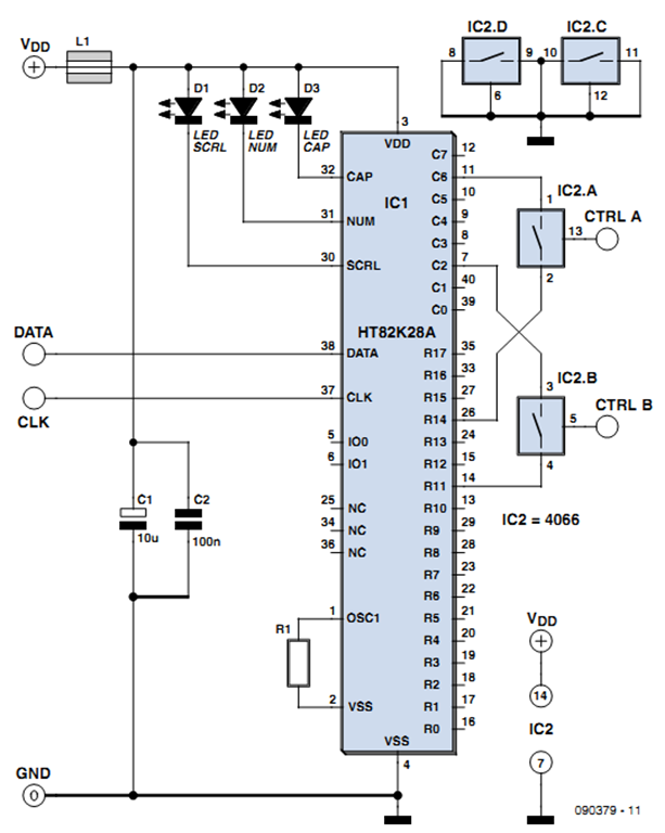
One of the more challenging aspects of creating a control or security system that utilizes a PC, such as a burglar alarm, is connecting the sensors to the computer. This typically requires specialized interface expansion boards, and programming that...

The relay power in the linear circuit is derived from a -120 V bias supply, while the transmit keying output from the Kenwood device is +12 V with a maximum current of 10 mA. A critical component of this...
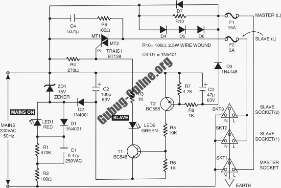
This circuit design features a modular arrangement that enables users to select only the modules best suited to their needs, allowing for the construction of a chain ranging from one to five modules in length. For those seeking a...
The performance indices of the telecontrol receiving decoding circuit are as follows: radio frequency (f) = 27 MHz, audio frequency (f) = 5.5 kHz, 100% modulation in square-wave form; radio frequency deviation is ±600 Hz, and the frequency shift...
This is an enhanced infrared (IR) remote control extender circuit that exhibits high noise immunity, resistance to ambient and reflected light, and an extended operational range of approximately 7 meters between the remote control and the extender circuit. It...
Warning: include(partials/cookie-banner.php): Failed to open stream: Permission denied in /var/www/html/nextgr/view-circuit.php on line 713
Warning: include(): Failed opening 'partials/cookie-banner.php' for inclusion (include_path='.:/usr/share/php') in /var/www/html/nextgr/view-circuit.php on line 713