
Permanent Magnet Detector
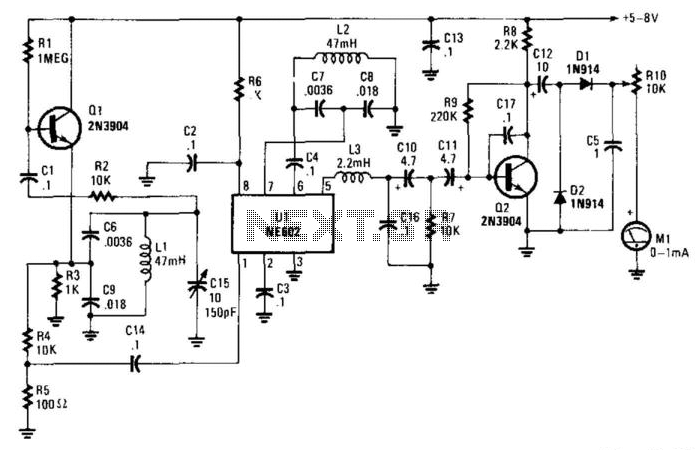
In this circuit design, oscillator Q1 is a critical component that generates a stable frequency of approximately 15 kHz. This frequency is essential for the operation of mixer U1, which serves to combine signals from different sources. The internal oscillator within U1 is synchronized to maintain the same frequency, facilitating effective mixing. Capacitor C15 plays a pivotal role in achieving zero-beat conditions, which is necessary for optimal mixing performance, ensuring that the two oscillators are phase-aligned.
The presence of a magnet near inductors L1 or L2 introduces a variable element to the circuit. The magnetic field alters the permeability of the inductor casings, causing a shift in the resonant frequency of the oscillators. This frequency modulation results in a change in the audio output, which is then subjected to filtering through the combination of inductor L3 and capacitors C16 and C10, along with resistor R7. This filtering stage is crucial for eliminating unwanted harmonics and noise, allowing only the desired audio signal to pass through.
The filtered audio signal is then amplified by transistor Q2, which boosts the signal strength to a level suitable for driving meter M1. The rectifiers D1 and D2 are employed to convert the amplified AC audio signal into a DC signal, which is necessary for the meter's operation. The design ensures that variations in the magnetic field can be accurately measured and displayed on meter M1, providing valuable feedback regarding the magnetic influence on the circuit. Overall, this circuit exemplifies the integration of oscillators, filters, and amplifiers to create a responsive system capable of detecting and indicating magnetic fields. In this circuit, oscillator Ql runs at about 15 kHz and feeds mixer Ul. Ul has an internal oscillator that runs a t around 15 kHz. CI5 is used to zero-beat both oscillators. When a magnet is brought near Ll or L2, the magnetic field shifts the permeability of their respective cases. This changes the oscillator frequency, and the audio note is passed through filter L3, C16, and C10/R7 to amplifier Q2, There the audio is amplified and drives meter Ml via rectifiers Dl and D2.
🔗 External reference
Related Circuits
This circuit is a two-wire light level detector. The power supply and output signal are delivered through the same wires, utilizing a current loop. This two-wire light level detector circuit operates by using a single pair of wires for both...
The TEM, specifically the Jeol 2000fx model, is equipped with two additional detectors: a secondary electron detector for SEM imaging and a STEM detector located at the bottom of the microscope. As the system dates back to the 1980s,...
The circuit was constructed using a few components powered by a 9 V battery for sensing the presence of bugs transmitting within the frequency modulation range. Frequency Modulation (FM) transmits its signal or information over a carrier wave by...
Dynamic flip-flops ignore pulses at their inputs that are shorter than 40 ns or do not have TTL levels. This means that TTL flip-flops are not well-suited for capturing noise pulses with unknown durations and magnitudes. This issue is...
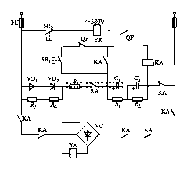
The DW15-200-630A breaker solenoid is a DC solenoid designed for short-time operation. The DK-1 control box utilizes an AC power switch to manage the electromagnet circuit, as depicted in Figure 6-7. The DK-1 type electromagnetic control box includes several...
The output of this circuit will be activated when a mix of two tones or frequencies is detected at the input. The frequency, denoted as f, is determined by the values of resistor R1 and additional components. This circuit is...
Warning: include(partials/cookie-banner.php): Failed to open stream: Permission denied in /var/www/html/nextgr/view-circuit.php on line 713
Warning: include(): Failed opening 'partials/cookie-banner.php' for inclusion (include_path='.:/usr/share/php') in /var/www/html/nextgr/view-circuit.php on line 713