
PFC Switching Power Supply
The PFC Switching Power Supply Circuit is designed to enhance the efficiency of power conversion while reducing harmonic distortion at the input stage. This circuit typically employs a PFC controller, which regulates the input current to follow the input voltage waveform, thereby improving the power factor towards unity.
The circuit can be implemented using a boost converter topology, where the input AC voltage is rectified to DC and then boosted to a higher DC voltage level. The PFC controller continuously monitors the input voltage and adjusts the duty cycle of the switching element, usually a MOSFET, to maintain the desired power factor.
Key components of the circuit include:
1. **Rectifier**: Converts AC input voltage to pulsating DC. Often a bridge rectifier is used to handle both halves of the AC waveform.
2. **Boost Converter**: Comprises an inductor, a diode, a switch (MOSFET), and a capacitor. The inductor stores energy when the switch is closed and releases it when the switch is open, boosting the voltage.
3. **PFC Controller**: This integrated circuit (IC) monitors the input voltage and adjusts the switching duty cycle to achieve a sinusoidal input current that is in phase with the input voltage.
4. **Filter Capacitor**: Smooths the output voltage to reduce ripple, ensuring stable operation of downstream components.
5. **Feedback Loop**: Provides real-time adjustments to the PFC controller based on the output voltage and current, contributing to overall circuit stability.
The design is particularly suited for applications requiring compact form factors, such as 1U rack-mounted systems, where space is limited. Additionally, the minimization of input harmonics is crucial for compliance with regulations such as IEC 61000-3-2, which governs harmonic emissions in electrical equipment.
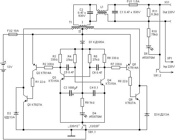
Overall, this circuit design not only enhances energy efficiency but also contributes to a cleaner power supply, reducing the environmental impact of electronic devices.The following circuit shows about PFC Switching Power Supply Circuit Diagram. Features: suited for 1U (1.75-inch), minimise input harmonic .. 🔗 External reference
Related Circuits
The 7815 regulates the positive supply, while the 7915 regulates the negative supply. The transformer should have a primary rating of 240/220 volts for Europe or 120 volts for North America. The center-tapped secondary coil should be rated approximately...
220 watts Uninterruptible Power Supply. Refer to the designated page for an explanation of the related circuit diagram for this power supply. The 220 watts Uninterruptible Power Supply (UPS) is designed to provide reliable backup power during outages, ensuring that...
This article addresses inquiries regarding a low-power FM transmitter designed to accept input from various sound sources, such as a guitar or microphone, and transmit on the commercial FM band. It is important to select an unused frequency on...
This project is a successor to SSTC1, which has been retired. The purpose of this coil is to operate with its breakout suppressed, demonstrating the concept of wireless power that Tesla himself worked on during his time. Further videos...

Dual power for each load refers to the operation of two power supplies working simultaneously to handle the electrical load. In the event of a power outage, a contact switch automatically closes all load circuits that are not powered...
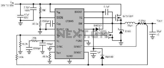
Burst Mode operation maintains high efficiency at light loads by reducing IC quiescent current to 120 µA. Light load efficiency is also improved with the reverse inductor current inhibit function, which supports discontinuous operation. Additional features include an adjustable...
Warning: include(partials/cookie-banner.php): Failed to open stream: Permission denied in /var/www/html/nextgr/view-circuit.php on line 713
Warning: include(): Failed opening 'partials/cookie-banner.php' for inclusion (include_path='.:/usr/share/php') in /var/www/html/nextgr/view-circuit.php on line 713