
Phone-recorder
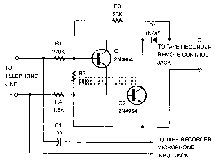
This recorder can be connected to telephone lines almost anywhere, and it does not require an external power source. The switch terminals of the tape recorder are connected to a pair of transistors configured as Darlington pairs, which are utilized to control the on and off operation of the recorder. When the telephone is off-hook, there is typically around 50 V DC across the phone line, which is divided among resistors R1, R2, and R4, ensuring that the base of transistor Q1 remains negative enough to keep the recorder in the off state. When the receiver is picked up, the voltage drops to 5 V. This voltage is insufficient to maintain Q1 in the cutoff region, allowing the recorder to activate. It is important to keep the recorder's switch in the on position, and depending on the number of users of the telephone, it may be necessary to rewind or change tapes periodically.
The described telephone line recorder operates by utilizing a simple yet effective transistor-based switching mechanism. The Darlington pair configuration enhances the current gain, allowing for the efficient control of the tape recorder with minimal voltage levels. The transistors Q1 and Q2 work in tandem; Q1 serves as the primary switch, while Q2 may provide additional amplification or stability in the circuit.
When the telephone is off-hook, the high voltage present across the line is divided by resistors R1, R2, and R4. This voltage division creates a biasing condition at the base of Q1, which remains negative enough to prevent conduction, thus keeping the recorder off. The resistors are selected based on their values to ensure that the voltage at Q1's base does not exceed the cutoff threshold during normal operation.
Upon lifting the receiver, the voltage drop to 5 V alters the biasing condition at the base of Q1. This change is critical as it transitions Q1 towards the active region, allowing current to flow through the collector-emitter path, thus activating the tape recorder. The current flowing through the Darlington pair enables the recorder to engage and start capturing audio from the telephone line.
It is essential to maintain the recorder's switch in the on position for continuous operation. Additionally, depending on the frequency of use and the number of users sharing the telephone line, users should monitor the tape's status, ensuring that it is either rewound or replaced as necessary to maintain optimal recording performance. This design exemplifies a practical application of transistor switching in telecommunication systems, providing a reliable means of recording phone conversations without the need for external power sources.This recorder can be connected to the telephone lines just about any place, and no external power source is needed. The tape recorder"s switch terminals are applied to a pair of transistors, connected as Darlingtons, that are used to turn the recorder on and off.
When the telephone is off-hook there"s usually about 50 Vdc across the phone that"s divided over Rl, R2, and R4, so that Ql"s base is negative enough to keep the recorder off. Pick up the receiver, and the voltage drops to 5 V. That leaves not quite-enough voltage on Ql"s base to keep that transistor at cutoff, so the recorder begins. Remember to keep your recorder"s switch in the on position, and depending on how many people use the telephone, remember to rewind or change tapes occasionally!
🔗 External reference