
Phono amplifier
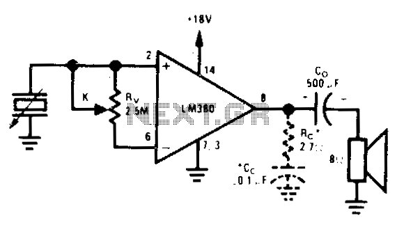
In electronic circuit design, achieving maximum input impedance is often critical, particularly in applications involving sensitive signal processing. The use of high input impedance circuits minimizes the loading effect on the preceding stage, thereby preserving the integrity of the signal. This is especially important in audio applications where voltage divider volume controls can introduce unwanted signal attenuation, negatively affecting audio quality.
To implement a circuit that maintains high input impedance, a buffer amplifier, such as a FET or an operational amplifier configured as a voltage follower, may be employed. This configuration allows the circuit to present a high input impedance while driving a lower impedance load effectively. The operational amplifier's feedback mechanism ensures that the output voltage closely follows the input voltage, thus preventing any significant voltage drop across the input.
In scenarios where a voltage divider is utilized for volume control, careful consideration must be given to the resistive values chosen. High resistor values can lead to increased input impedance but may also introduce noise and susceptibility to interference. Conversely, lower resistor values can mitigate these issues but at the cost of reduced input impedance. Therefore, a balance must be struck between achieving the desired volume control and maintaining high input impedance.
In summary, when designing circuits that require maximum input impedance, especially in the context of volume control, it is essential to consider the implications of using voltage dividers and to utilize buffering techniques to ensure signal integrity and quality.Used when maximum input impedance is required or the signal attenuation of the voltage divider volume control is undesirable. 🔗 External reference
Related Circuits
Schematic and description of a simple microphone amplifier circuit. This circuit contains two stages: the first is a microphone preamplifier, and the second is an audio amplifier using the LM386 Amplifier IC. The simple microphone amplifier circuit is designed to...
The DC-10 MHz amplifier shown below is identical for both scope channels. The input FET should be mounted directly on the adjustable attenuator switch for best frequency response. The vertical position pots, R27 and R51, change the dc level...
A popular project among microcontroller enthusiasts is to build a radio-controlled clock. Tiny receiver boards are available, featuring a pre-adjusted ferrite. The radio-controlled clock project leverages a microcontroller to receive time signals transmitted from a time signal transmitter, typically operated...
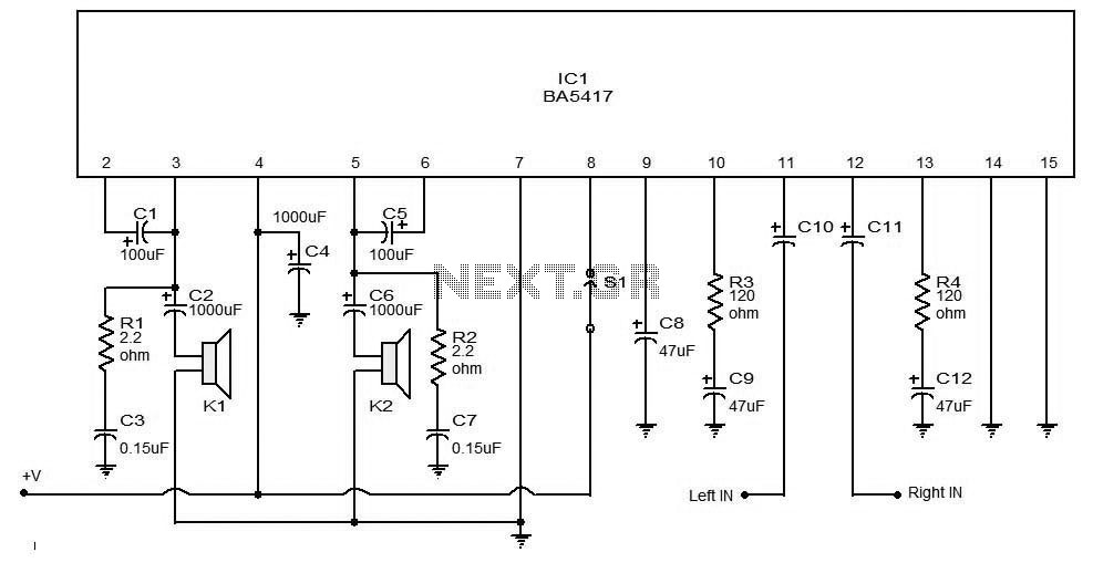
The BA5406 is a dual OTL (output transformerless) monolithic power integrated circuit (IC) featuring two high-output speaker amplifier circuits. It operates effectively with a supply voltage (Vcc) of 12 V and a load resistance (Rl) of 3 Ohms. At...
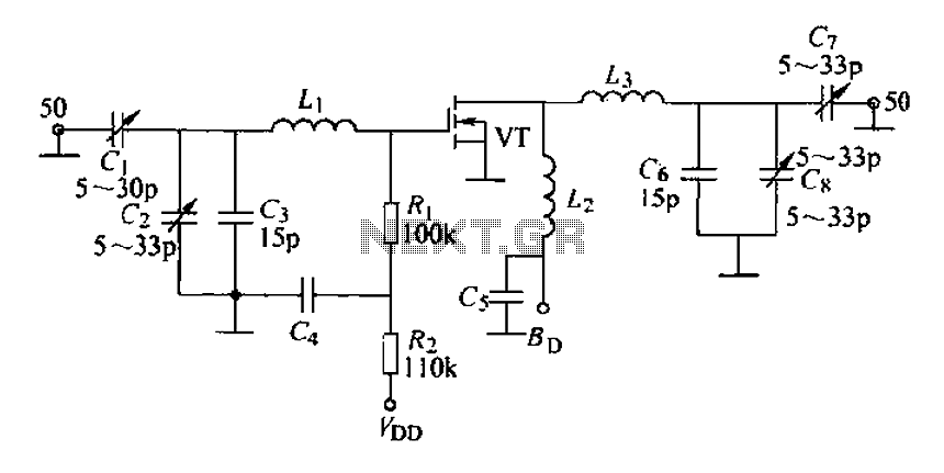
A 175 MHz high-frequency amplifier circuit utilizing a field-effect transistor (FET) is presented. The field-effect transistor used is the 3D04H, along with its associated components and parameters. The 175 MHz high-frequency amplifier circuit is designed to amplify signals in the...
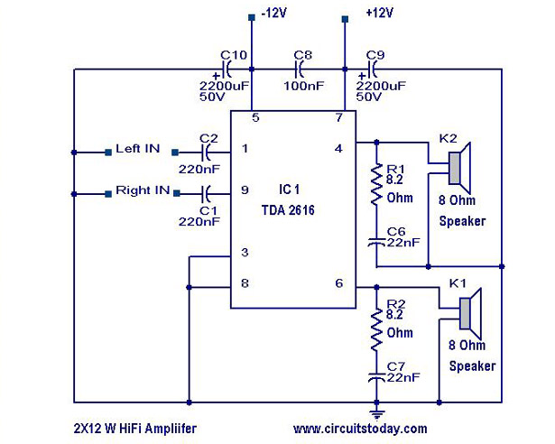
A simple Hi-Fi amplifier circuit diagram with a schematic for creating an audio amplifier, designed using the TDA 2616 integrated circuit (IC), which is a stereo power amplifier. It is suitable for use with radios, tape players, and televisions,...
Warning: include(partials/cookie-banner.php): Failed to open stream: Permission denied in /var/www/html/nextgr/view-circuit.php on line 713
Warning: include(): Failed opening 'partials/cookie-banner.php' for inclusion (include_path='.:/usr/share/php') in /var/www/html/nextgr/view-circuit.php on line 713