
Photo relay circuit
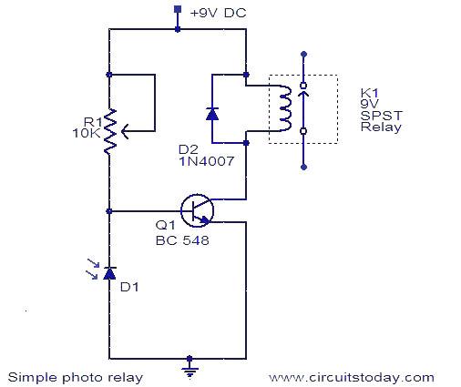
The photo relay circuit operates through a straightforward mechanism that hinges on the properties of the photodiode and transistor. In the absence of light, the photodiode maintains a high resistance, which prevents significant current flow. This condition keeps the voltage across it at a level that does not suffice to forward bias the transistor Q1, thereby ensuring that the relay remains in the OFF state and the load remains disconnected.
Upon exposure to light, the photodiode's resistance drops as the minority carrier current increases. This change results in a lower voltage across the photodiode. If the voltage surpasses the threshold required to forward bias Q1, the transistor conducts, allowing current to flow through the relay coil. As a result, the relay contacts close, connecting the load to the power supply.
Moreover, the inclusion of diode D2 is crucial for protecting the transistor from voltage spikes that can occur when the relay coil is de-energized. These transients, generated by the collapsing magnetic field of the relay, can induce back electromotive force (EMF) that may damage the transistor. The freewheeling diode provides a path for this induced current, effectively clamping the voltage and safeguarding the transistor.
Overall, this circuit configuration exemplifies an effective method for controlling a load based on light intensity, leveraging the unique characteristics of photodiodes and transistors, while ensuring reliability through protective components.A photo relay or light activated relay is a circuit which opens and closes the relay contacts according to the light. Here a photo diode is used to sense the light. The photo diode offers a high resistance when there is no light falling on it. Here the photo diode is connected in reverse biased condition. The only current flowing through it will be du e to the minority carriers. When light falls on it, the current due to the minority carriers increase and the diode offers a low resistance. As a result the voltage across the diode will not be sufficient to make the transistor Q1 forward biased and the relay will OFF.
When there is darkness the photo diode resistance increases and the voltage across it will become enough to forward bias the transistor Q1 making the relay ON. The diode D2 is used as a freewheeling diode to protect the transistor from transients produced to the switching of relay.
By this way the load connected through the relay contacts can be switched ON and OFF according to the light falling on the photo diode. 🔗 External reference
Related Circuits
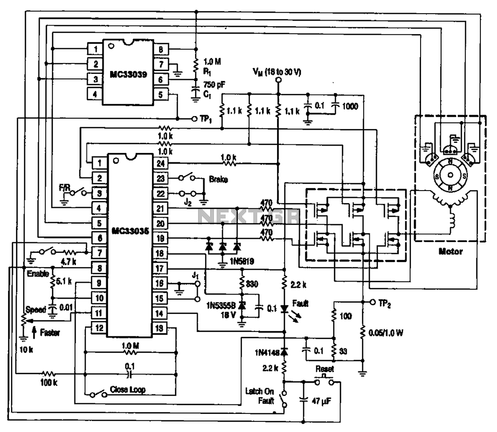
The brushless DC motor control circuit utilizing the MC33035 and MC33039 chips employs a combination of control circuits as illustrated in the figure. The primary components include the MC33035 motor control chip, the MC33039 brushless motor adapter, field effect...
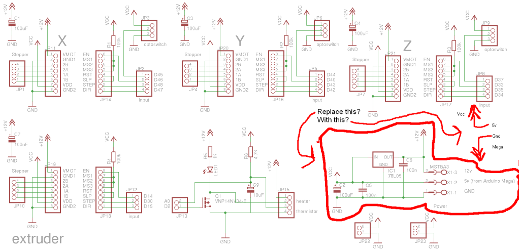
Preparing to assemble Adrian's Pololu stepper driver circuit has raised a question. He indicates that if using 5V from the Arduino Mega, the 78L05 voltage regulator should be omitted. This is a positive development, although there is an incorrect...
At low output power, up to 18 W, the device functions as a standard BTL amplifier. When a greater output voltage swing is necessary, the internal supply voltage is increased using external electrolytic capacitors. This momentarily elevated supply voltage...
The RF power amplifier circuit described here utilizes the transistors 2SC1970 and 2N4427. This FM RF amplifier operates within the frequency range of 88-108 MHz, delivering an output power of approximately 1.3W from an input driver of 30-50mW. The...
The LM1036 is a DC-controlled circuit designed for managing tone (bass/treble), volume, and balance in stereo applications, such as car radios, televisions, and audio systems. It features an additional control input for easy loudness compensation. Four control inputs allow...
To achieve optimal audio reproduction at various listening levels, it is essential to incorporate tone-setting controls that align with the well-documented characteristics of human auditory perception. Specifically, human ear sensitivity exhibits a non-linear response across the audible frequency spectrum,...