
Photo Strobe Slave Trigger Circuit
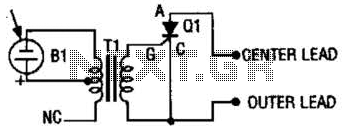
The photo strobe slave trigger circuit operates by harnessing the energy from ambient light to initiate a flash in response to a primary strobe light source. The solar cell, typically a small photovoltaic cell, converts light energy into electrical energy, producing a voltage output that is proportional to the intensity of the light it receives. When the master strobe is activated, it emits a burst of light that strikes the solar cell.
Upon receiving this light, the solar cell generates a small voltage, which is sufficient to trigger the SCR. The SCR, a semiconductor device that acts as a switch, remains off until it is triggered by a voltage applied to its gate terminal. Once the SCR is activated by the voltage from the solar cell, it allows current to flow through the strobe light circuit, causing the connected strobe to flash.
This circuit design is advantageous for photographers who require multiple flashes synchronized with a primary light source without the need for complex wiring or additional triggering mechanisms. The simplicity of the solar cell-based trigger allows for portability and ease of use in various lighting conditions. Additionally, the use of an SCR provides reliable switching capabilities, ensuring that the strobe light will flash promptly when triggered.
Overall, the photo strobe slave trigger circuit exemplifies an efficient and innovative solution for enhancing photographic lighting setups, enabling photographers to achieve creative effects with minimal equipment. The photo strobe slave trigger circuit uses a solar cell and an SCR to flash any strobe when you trigger your master strobe. The tiny solar cell produces a very small voltage when light falls on its surface. 🔗 External reference
Related Circuits
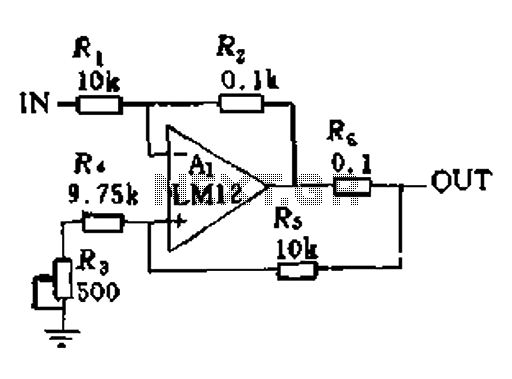
In a servo system, the current drive connection is frequently utilized. The output current (IOUT) is proportional to the input channel number (y). Using the current drive mode can mitigate issues caused by the motor's large inductance, which induces...

This circuit is useful for a bench supply in the lab. Separate or tracking operation is possible. The regulators should be properly heatsinked. Tl is a 24-Vac wall transformer of suitable current capacity. The described circuit functions as a laboratory...
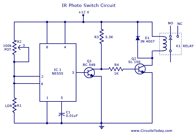
A simple photo switch circuit using an NE 555 IC with a diagram and schematic. This photo switch activates a relay when light intensity crosses a specified limit. It is a light sensor circuit suitable for home and industrial...
When the doorbell switch K1 is pressed, the doorbell rings and LED D3 lights up. If there is no one to answer the door, guests will leave, but D3 remains illuminated, indicating that visitors have arrived. The circuit includes...

The astable multivibrator circuit lacks a stable state. In the absence of an external signal, the internal transistors alternately switch between cutoff and saturation at a frequency determined by the RC time constants of the coupling circuits. Therefore, an...
The program utilizes the internal 4 MHz oscillator of the PIC16F628 microcontroller in a two-input alarm circuit. The two-input alarm circuit designed with the PIC16F628 microcontroller leverages the internal 4 MHz oscillator to provide a stable clock signal for operation....
Warning: include(partials/cookie-banner.php): Failed to open stream: Permission denied in /var/www/html/nextgr/view-circuit.php on line 713
Warning: include(): Failed opening 'partials/cookie-banner.php' for inclusion (include_path='.:/usr/share/php') in /var/www/html/nextgr/view-circuit.php on line 713