
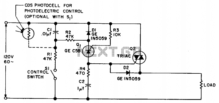
Photoelectric switch
It is particularly suitable for applications where radio frequency interference (RFI) and audio filtering are not acceptable, where transformer magnetizing inrush currents can lead to nuisance fuse-blowing, and where sensitive equipment must function near power switches.
Synchronous switching circuits are designed to enhance the efficiency of power management in various electronic applications. The core principle involves precise timing to ensure that switching occurs at zero voltage and current, which minimizes electrical stress and reduces electromagnetic interference. This technique is critical in applications like lighting control systems, motor drives, and power supplies for sensitive electronics.
The circuit typically includes a zero-crossing detector that monitors the AC waveform. This component triggers the switching mechanism, which can be a solid-state relay (SSR) or a thyristor, ensuring that the load is connected or disconnected at the optimal moment. The use of a cadmium-sulfide photocell as a variable resistance allows for light-sensitive applications, enabling automatic adjustments based on ambient light conditions.
In environments where RFI is a concern, synchronous switching circuits improve overall system performance by reducing noise emissions during the switching process. This is particularly important in audio equipment and communication devices, where unwanted interference can degrade performance.
Furthermore, the ability of the circuit to conduct an integral number of cycles is advantageous in preventing sudden inrush currents that can cause fuses to blow or circuit breakers to trip. This feature is especially beneficial in transformer applications, where inrush current can be several times the normal operating current.
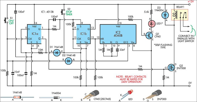
Overall, synchronous switching circuits provide a robust solution for managing AC loads with minimal disruption, enhancing both performance and reliability in a wide range of electronic systems.Synchronous switching is turning on only at the instant the ac supply voltage passes through zero, and turning off only when current passes through zero. This circuit provides this function in response to either a mechanical switch or a variable resistance such as a cadmium-sulfide photocell.
This circuit produces the minimum disturbance to the power supply when switching, and always conducts an integral number of whole cycles. It is ideal for use wherever RFI and audio filtering is undesirable, where magnetizing inrush current of transformers causes nuisance fuse-blowing, and where sensitive equipment must operate in the vicinity of power switches. 🔗 External reference
Related Circuits
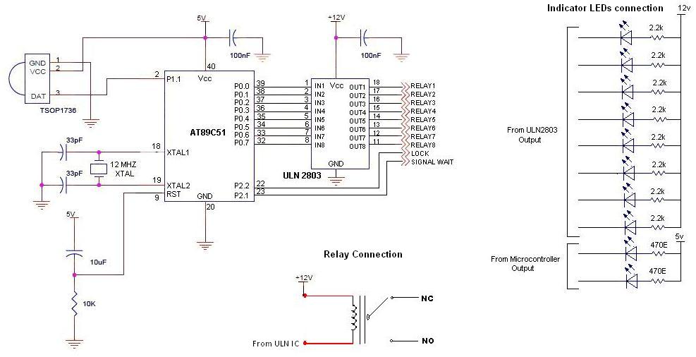
To control multiple switches, it is necessary to transmit several bits via infrared (IR) transmission to indicate which key is pressed on the remote control and, consequently, which switch on the switchboard to operate. This project utilizes a commercially...
The circuit described here was designed as an addition to a remotely controlled garage door opener. The problem was that a brief burst of interference, arising from a thunderstorm or a mains spike, was enough to trigger the mechanism,...
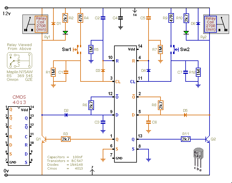
This versatile circuit offers a selection of different switching modes. It can function as two entirely separate toggle switches, with each push button successively energizing and de-energizing its corresponding relay. Alternatively, the two switches can be interconnected with diodes...
The system utilizes a single circuit breaker instead of fuses. According to the schematic, switches provide 12 volts of power and ground to the window motors in opposite polarities, allowing the windows to move up and down. Troubleshooting should...
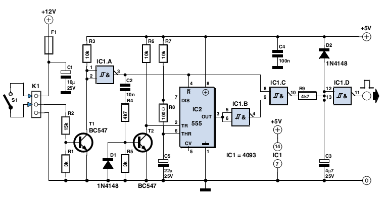
This 9-minute timer switch is designed to control lighting in a toilet or bathroom. The timer is activated by pressing switch S1 and deactivated by pressing S1 again. If the switch is not turned off, the light will automatically...
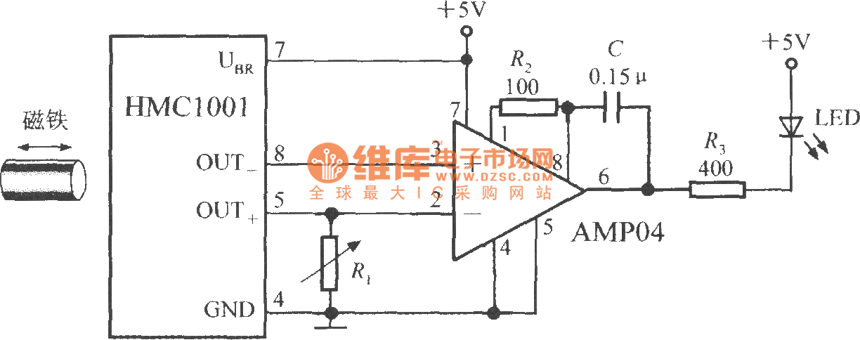
The proximity switch circuit consists of the HMC1001 sensor, operational amplifier (AMP04), and a light-emitting diode (LED). The operational amplifier functions as a comparator. When a magnet, measuring between 6mm and 12mm, is moved to a predetermined position near...
Warning: include(partials/cookie-banner.php): Failed to open stream: Permission denied in /var/www/html/nextgr/view-circuit.php on line 713
Warning: include(): Failed opening 'partials/cookie-banner.php' for inclusion (include_path='.:/usr/share/php') in /var/www/html/nextgr/view-circuit.php on line 713