
Photomultiplier Supply Circuit

The Cockcroft-Walton voltage multiplier is a type of DC-DC converter that generates high voltages from a low-voltage source. It operates by utilizing a series of capacitors and diodes arranged in a ladder-like configuration. Each stage of the multiplier increases the output voltage by rectifying and charging capacitors to the peak input voltage, effectively stepping up the voltage with each stage.
In the context of photomultiplier tubes, the dynodes require a specific high-voltage potential to amplify the photoelectrons generated by incident photons. The Cockcroft-Walton multiplier is advantageous because it can achieve high voltages efficiently while minimizing power loss typically associated with resistive voltage dividers. This efficiency is critical in applications where power conservation is paramount, such as in portable or battery-operated devices.
The design of a Cockcroft-Walton multiplier involves careful selection of component values, including the capacitance of the capacitors and the reverse voltage ratings of the diodes, to ensure reliable operation at the required output voltage. The layout must also consider the physical spacing between components to prevent arcing at high voltages.
The output voltage can be calculated based on the number of stages and the input voltage. For instance, if a 10-stage multiplier is used with an input voltage of 10V, the output can theoretically reach up to 100V, assuming ideal conditions. However, real-world factors such as load resistance and diode forward voltage drop must be accounted for in practical applications.
Overall, the Cockcroft-Walton voltage multiplier is a crucial circuit in high-voltage applications, particularly in photomultiplier tube systems, where it provides the necessary voltage amplification without significant energy loss. A Cockcroft-Walton voltage multiplier supplies the stepped voltage required for the dynodes of the PMT without the power-wasting voltage- divider resistor string that is traditionally used.
Related Circuits

This circuit is particularly beneficial for hobbyists using a breadboard to experiment with ideas, as well as those employing a simple homemade DC power supply that consists of a transformer, rectifier, smoothing capacitor, and protective fuse, specifically one lacking...
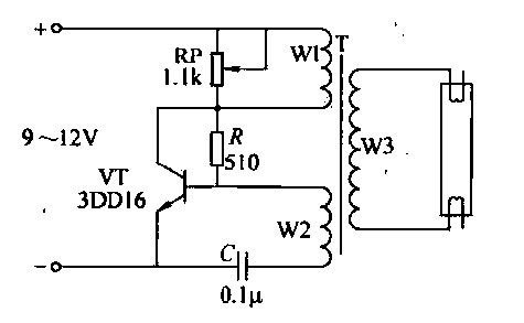
This circuit is designed for the ignition of a direct current (DC) fluorescent lamp rated between 6 to 8 watts. It utilizes a common pole-blocking oscillator that consists of a transistor (VT) and is induced by the secondary side...
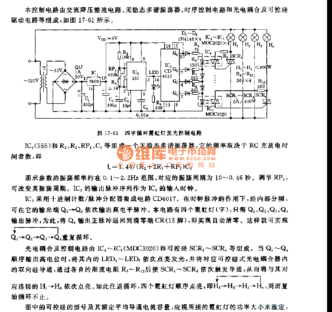
This control circuit consists of an AC step-down rectifier circuit, an astable multivibrator, a timing control circuit, an optocoupler circuit, and an SCR driving circuit, as illustrated in Figure 17-61. The astable multivibrator is formed using IC2 (555), resistors...
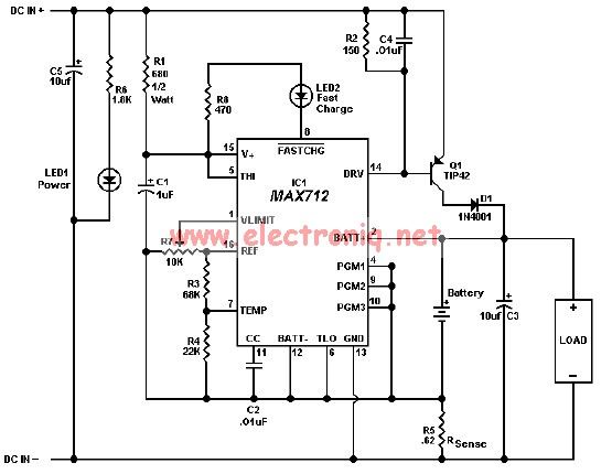
The MAX712 charger requires a power supply with an output voltage that is at least 1.5V higher than the maximum battery voltage. Charge completion is determined by a voltage-slope detecting analog-to-digital converter, a timer, and a temperature window comparator. The...

More: The input data contains a brief description with no additional context or information provided. In the realm of electronics, a circuit schematic typically serves as a visual representation of an electrical circuit. It illustrates the various components such...

A CMOS logic gate is utilized in this circuit. When an object approaches the antenna, the change in oscillator output is detected by components 1)1 and 1)2, which is then amplified by U1C. This amplification drives Q1, activating alarm...