
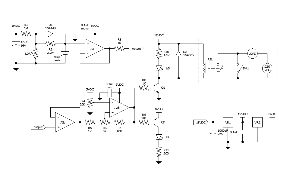
Photovoltaic Light Sensors In Solar Tracker
The photovoltaic light sensor circuit is designed to optimize the alignment of solar panels with respect to the sun's position, thereby enhancing energy capture efficiency. The core of the system consists of multiple photovoltaic cells that detect light intensity from different angles. These cells generate a voltage output proportional to the light they receive.
In a typical single-axis solar tracker, two or more light sensors are strategically placed on the surface of the solar panel. The output from these sensors is processed by a microcontroller or comparator circuit, which compares the voltage levels produced by each sensor. When one sensor detects more light than the other, the microcontroller sends a signal to a motor driver circuit, which adjusts the angle of the solar panel to face the light source directly.
The circuit design emphasizes cost-effectiveness by utilizing readily available components such as operational amplifiers for signal comparison and low-cost DC motors for adjustment. The simplicity of the design allows for easy implementation and maintenance, making it suitable for both residential and commercial solar applications.
To ensure accurate tracking, the circuit may include additional features such as hysteresis to prevent rapid oscillations in panel position due to fluctuating light levels. Furthermore, it may incorporate a feedback mechanism to monitor the panel's position and adjust it accordingly, ensuring optimal performance throughout the day.
Overall, this photovoltaic light sensor circuit exemplifies a practical solution for maximizing solar energy harvesting through efficient tracking mechanisms.The following circuit shows about Photovoltaic Light Sensors In Solar Tracker. Features: accurate, low cost, simple, single axis electronic solar .. 🔗 External reference
Related Circuits
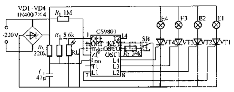
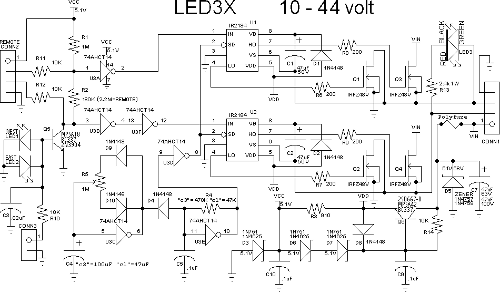
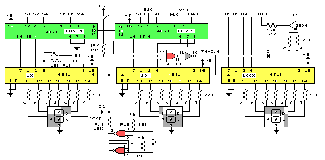
The ASIC is a flashing light string controller featuring four outputs. It includes a single key cycle control with six different lighting effects, and it allows for the selection of either 16 or 8 patterns. The circuit incorporates a...
Approximately ten days ago, an all-linear automatic night light circuit was installed to control the lights in the living room. The circuit comprises three operational amplifiers (op-amps): two configured as voltage followers and one as a comparator. As depicted...
This device is a combination digital clock timer and solar panel charge controller designed to maintain a deep cycle battery charged by a solar panel. The timer output controls a 12-volt load for a 32-minute interval each day. The...
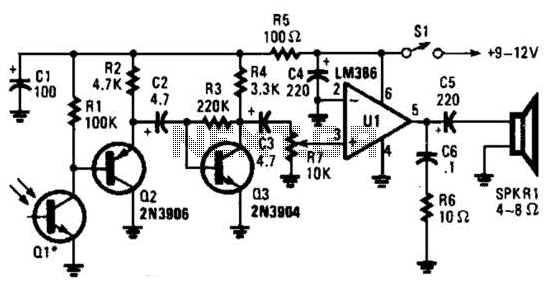
This receiver for amplitude-modulated light signals utilizes a phototransistor Q1 mounted within a parabolic reflector to enhance its range. Any NPN phototransistor is suitable for this application. An emitter-follower configuration using Q2 drives an amplifier stage Q3. The output...
An automatic multipurpose emergency lights circuit is presented. Typically, emergency lights are connected to the mains for standby when fully charged. In the event of a sudden power failure, the ambient light transitions from strong to weak, indicating a...
This circuit utilizes a probe that contains a Clairex 905HN light-dependent resistance element, which is connected to a DC differential amplifier. The amplifier drives a meter with a specially calibrated scale. The article outlines the calibration procedure. A switching...
Warning: include(partials/cookie-banner.php): Failed to open stream: Permission denied in /var/www/html/nextgr/view-circuit.php on line 713
Warning: include(): Failed opening 'partials/cookie-banner.php' for inclusion (include_path='.:/usr/share/php') in /var/www/html/nextgr/view-circuit.php on line 713