
pic based modified sine wave inverter
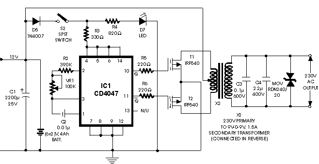
The proposed circuit design incorporates a microcontroller from the PIC family, which serves as the main control unit for the inverter operation. The two P-channel MOSFETs (F9540N) are employed as the primary switching elements, facilitating the conversion of DC voltage to AC voltage. The center-tapped transformer is crucial for stepping up the voltage to the desired level, providing a 230V output from a 12V input.
In this configuration, the microcontroller generates the necessary PWM (Pulse Width Modulation) signals to control the gates of the MOSFETs. The switching sequence of the MOSFETs is critical to ensure that they operate in a complementary manner, allowing for the creation of an alternating current (AC) waveform. The center-tapped transformer provides isolation between the input and output sides, enhancing safety and performance.
The F9540N MOSFETs are selected for their high efficiency and low on-resistance, which minimizes power losses during operation. The gate drive circuitry must be designed to ensure that the MOSFETs are fully turned on and off, which may involve the use of gate drivers or additional components to manage the switching speeds and prevent cross-conduction.
The circuit should also include protection mechanisms such as diodes for back EMF protection, fuses for overcurrent protection, and possibly a feedback loop to monitor the output voltage and adjust the PWM signals accordingly to maintain a stable output. Proper heat sinking for the MOSFETs is essential to manage thermal performance during operation.
Overall, this PIC-based inverter circuit design offers a compact and efficient solution for converting low-voltage DC power into high-voltage AC power, suitable for various applications in power electronics.hi am trying to make a pic based inverter circuit. the circuit uses 2 p-channel mosfets(f9540n) with a centre tapped 12-012/230v transformer. i.. 🔗 External reference
Related Circuits
Connect a PIC microcontroller to an RN-41 Bluetooth module. The PCB was not designed by the current user, so the rationale behind the circuit's design, which differs from the voltage divider method used by others, is unclear. The 5V...

In the image above, Oscium's iMSO-104 oscilloscope is measuring the output waveform of an infrared receiver (IR Rx). The iPad and iMSO serve as the oscilloscope to measure the receiver's output signal as the alignment between the transmitter and...
When first encountering this article, it is apparent that it presents an excellent project utilizing only a few components. Microcontroller projects based on LEDs are particularly appealing. This project involves the design and implementation of a microcontroller-based LED circuit, which...

This circuit is a 300W inverter power converter, which takes a 24V input battery and outputs 220V AC at 50Hz with a maximum power of 300W. The main components used in this circuit include the IC CD4027, NE555, CA3130,...
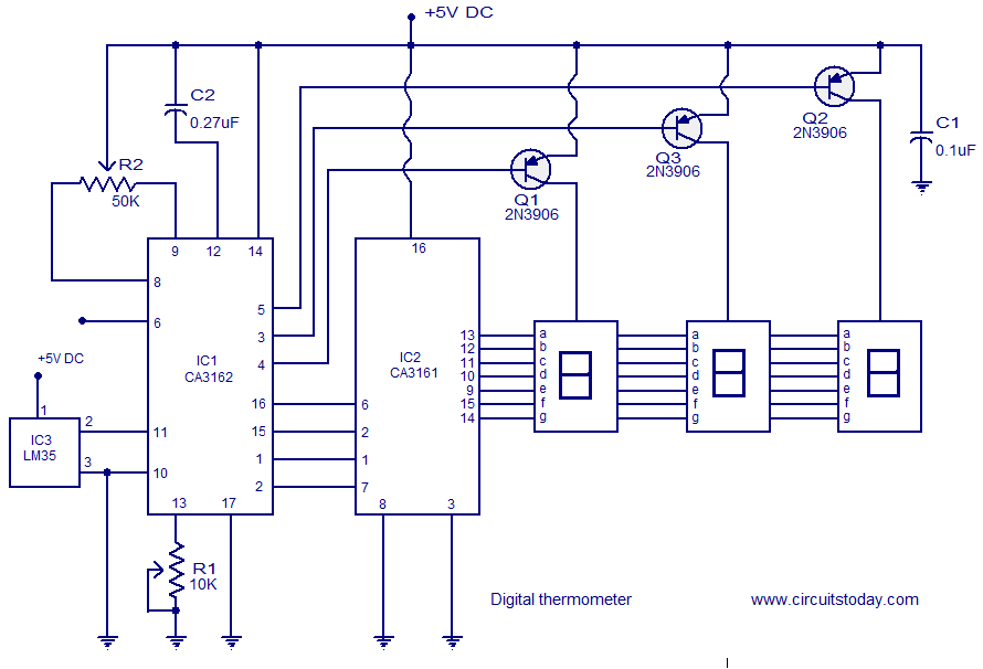
A simple digital thermometer circuit without a microcontroller and featuring a seven-segment LED readout is presented. The circuit utilizes three integrated circuits (ICs): CA3162, CA3161, and LM35. The CA3162 is a monolithic analog-to-digital (A/D) converter with a BCD output....
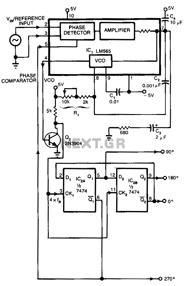
Many applications require control signals that have phase shifts relative to an input signal. This circuit accepts a sine, square, or triangular wave as an input reference signal and produces square-wave outputs with 0°, 90°, 180°, and 270° phase...
Warning: include(partials/cookie-banner.php): Failed to open stream: Permission denied in /var/www/html/nextgr/view-circuit.php on line 713
Warning: include(): Failed opening 'partials/cookie-banner.php' for inclusion (include_path='.:/usr/share/php') in /var/www/html/nextgr/view-circuit.php on line 713