
PIC Current Limiter

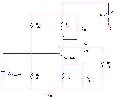
The described circuit primarily addresses the current management in stepper motors used in RepRap applications. The absence of current limiting in the PIC/Generation 1 electronics necessitates reliance on the inherent resistance of the stepper motors to prevent excessive current draw. This design choice poses a challenge, particularly as many commercially available stepper motors exhibit lower resistance values, leading to potential overcurrent situations.
The schematic for a single coil indicates that each stepper motor is composed of two coils, which are essential for the motor's operation. To effectively monitor and manage the current through these coils, comparators are employed. The LM393, a dual comparator, can be used for this purpose; however, using an LM339, which contains four comparators, offers a more efficient solution. This approach allows for the monitoring of all four coils associated with two motors, optimizing component usage and reducing overall circuit costs.
In this configuration, the comparators will be set up to compare the voltage across the coil with a reference voltage that corresponds to the desired current limit. If the voltage exceeds the reference, indicating that the current is too high, the comparator output can trigger a control mechanism to reduce the power supplied to the motor, thus protecting the circuit from damage due to overcurrent conditions.
The implementation of the LM339 in this context not only simplifies the design but also enhances reliability, as fewer components are required. The overall circuit can be designed to ensure that each coil operates within safe limits, promoting longevity and performance in the stepper motors utilized in 3D printing applications.The PIC/Generation 1 electronics do not have any form of current limitting. They rely on the stepper motors resistance to keep the current below 2 Amps at 12 Volts. Unfortunatly the more commonly available Steppers of the size used in RepRap have much lower resistances. e. g. The current BitsFromBytes supplied Steppers have a resistance of XXXX. Be low is the schematic for a single coil, each stepper motor has two coils. As each coil requires one comparator an LM393 (dual comparator) could be used. It is almost certainly cheaper though to use an LM339 (quad comparator) and build the circuit to handle 4 coils / 2 motors. 🔗 External reference
Related Circuits
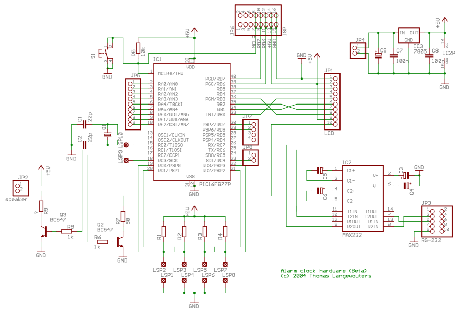
This project outlines a digital clock featuring an alarm function, utilizing a PIC16F877 microcontroller to achieve an accurate 1-second delay with Timer0 through Roman's zero error method. The time is displayed in large font on a 4G—20 character LCD,...
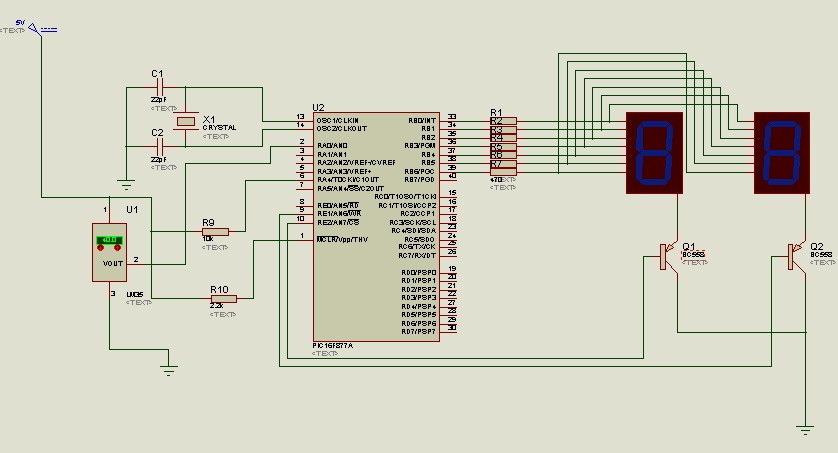
The circuit utilizes the LM35 temperature sensor to measure temperature in the range of 0 to 99 degrees Celsius and displays the readings using two seven-segment displays. It is designed to activate devices through the RC pins; for instance,...
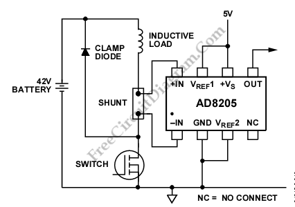
The AD8205 can be utilized to create a high-side current sensing circuit with a low-side switch. In this configuration, an inductive load (such as a solenoid) and a resistive shunt are incorporated. The resistive shunt is positioned on the...
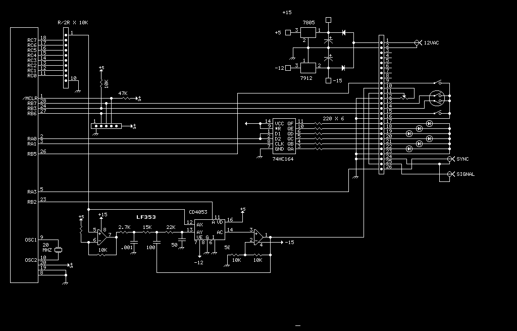
After the recent demise of our multifunction signal generator, we decided to make one of our own. The circuit uses a PIC16F870 (about $3), an R/2R resistor ladder network (for a real fast and cheap D/A), and a few...
A simulation of a 27 MHz transmitter circuit is to be conducted using PSPICE. The circuit diagram is provided as Figure 1 in the following content. The 27 MHz transmitter circuit typically consists of several key components, including an oscillator,...
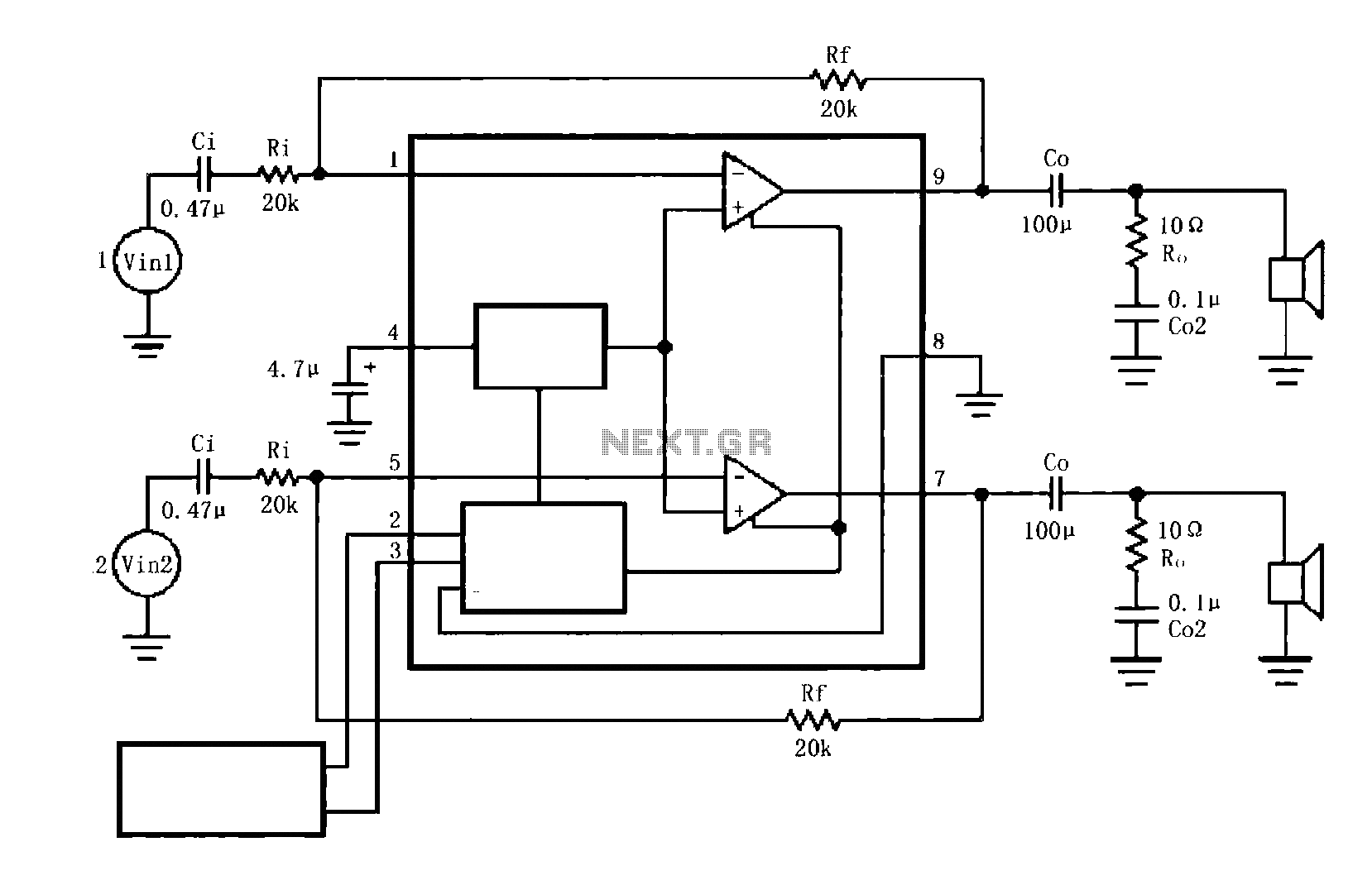
The circuit illustrated is a typical configuration for the LM4916 two-channel amplifier. The left and right channel audio signals are fed into the LM4916, which amplifies them internally. The output is then delivered through a coupling capacitor (Co) to...
Warning: include(partials/cookie-banner.php): Failed to open stream: Permission denied in /var/www/html/nextgr/view-circuit.php on line 713
Warning: include(): Failed opening 'partials/cookie-banner.php' for inclusion (include_path='.:/usr/share/php') in /var/www/html/nextgr/view-circuit.php on line 713