
pic frequency counter
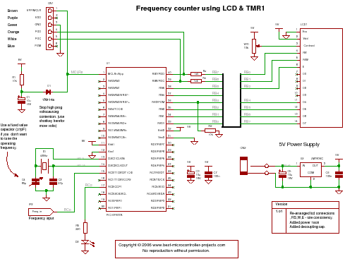
This frequency counter project is designed to measure input signal frequencies up to 50 MHz, making it suitable for a variety of applications in electronics and communications. The core of the project is based on a PIC microcontroller, which is programmed using C code to accurately process the incoming signal.
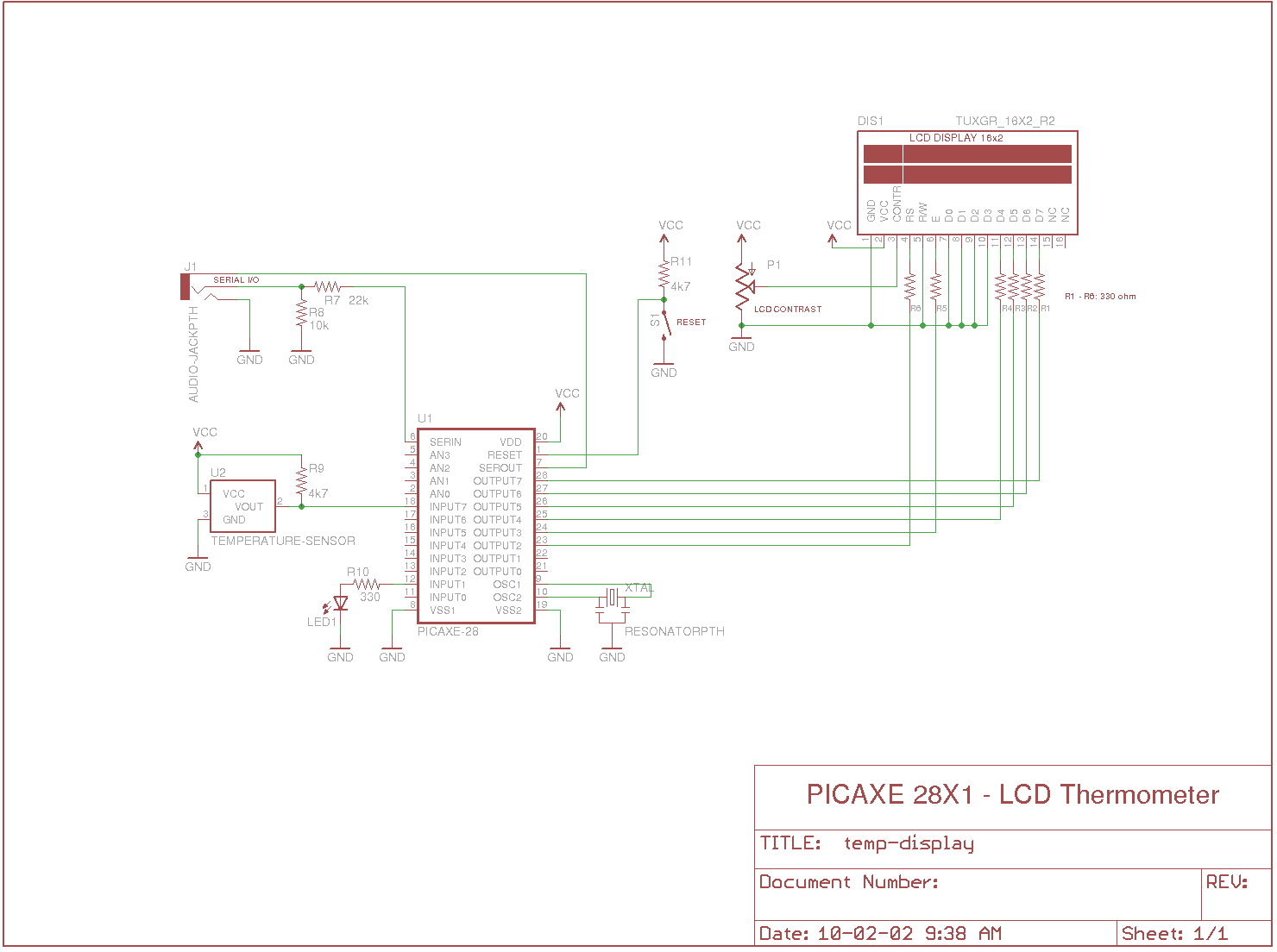
The HD47880 LCD serves as the user interface, providing a clear visual representation of the measured frequency. The LCD typically operates in a 4-bit or 8-bit mode, and it is initialized and controlled through the microcontroller's GPIO pins. The display will show the frequency value in Hertz (Hz), updating in real-time as the input frequency changes.
Timer 1 of the PIC microcontroller is configured in capture mode, which allows it to count the rising or falling edges of the input signal. This timer is crucial for accurately measuring the frequency, as it can record the time intervals between successive edges. The microcontroller's firmware will calculate the frequency by counting the number of edges detected within a defined time period and then converting that count into a frequency value.
To ensure proper operation, the input signal must be conditioned if necessary, such as through signal amplification or filtering, to maintain signal integrity and avoid false triggering. The design may also include a debounce mechanism to filter out noise and ensure that only valid edges are counted.
Overall, this frequency counter represents a practical application of microcontroller technology in measuring and displaying high-frequency signals, with potential uses in testing and troubleshooting electronic circuits.and C code for a PIC frequency counter operating up to about 50MHz. The project uses an HD47880 LCD for the display and uses timer 1 to count edges of the input signal.. 🔗 External reference
Related Circuits
The circuit this month is a simple 8 light chaser built around a PIC. This will demonstrate how easy it is to program a PIC and to utilize it in a circuit. The circuit works as follows. When power...
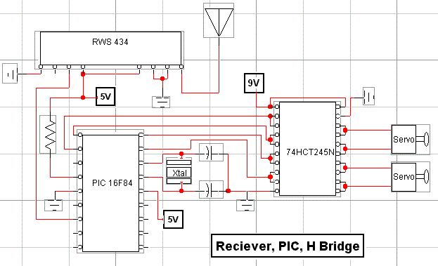
RF technology is an exciting field to incorporate into electronic designs. However, for beginners, constructing reliable RF transmitters and receivers can be challenging. RF (Radio Frequency) technology plays a crucial role in modern communication systems, enabling wireless data transmission over...
This is a design for a frequency meter based on AVR microcontrollers. Maximum input frequency is specified to be 30 MHz in the multi-chip configuration, and in single-chip configuration, there are both 5 MHz and 10 MHz versions operating...
Measures the temperature using the DS18B20 temperature sensor, displays the reading on a 2x16 character LCD, sends the data to a serial terminal, and checks the temperature against predefined limits. The output is set high if the temperature is...
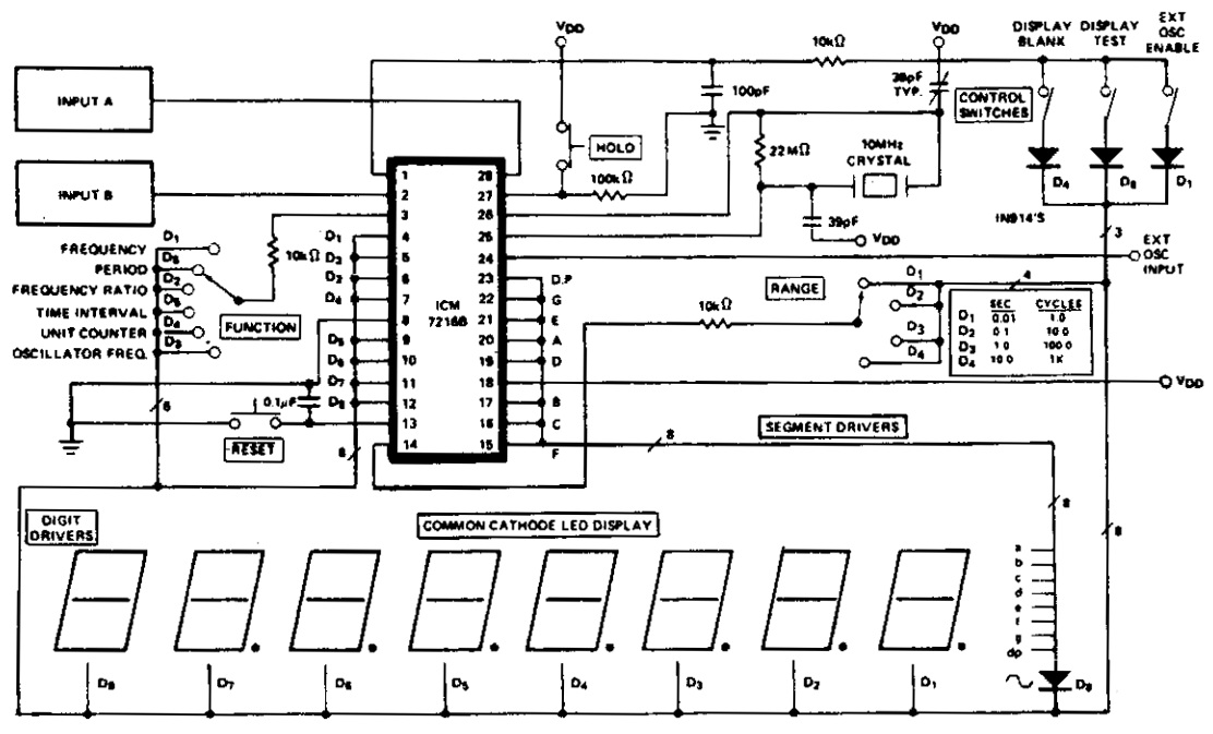
The ICM7216A can be utilized as a minimal component complete Universal Counter. This circuit is capable of handling input frequencies of up to 10 MHz at INPUT A and 2 MHz at INPUT B. In cases where the signal...
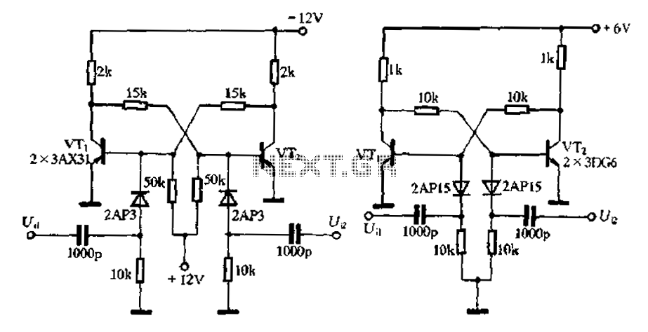
Bistable circuit operating at a frequency of 10 kHz or lower. A bistable circuit, also known as a flip-flop, is a fundamental building block in digital electronics. It has two stable states and can store one bit of data. The...
Warning: include(partials/cookie-banner.php): Failed to open stream: Permission denied in /var/www/html/nextgr/view-circuit.php on line 713
Warning: include(): Failed opening 'partials/cookie-banner.php' for inclusion (include_path='.:/usr/share/php') in /var/www/html/nextgr/view-circuit.php on line 713