
Picture-fixer-inverter
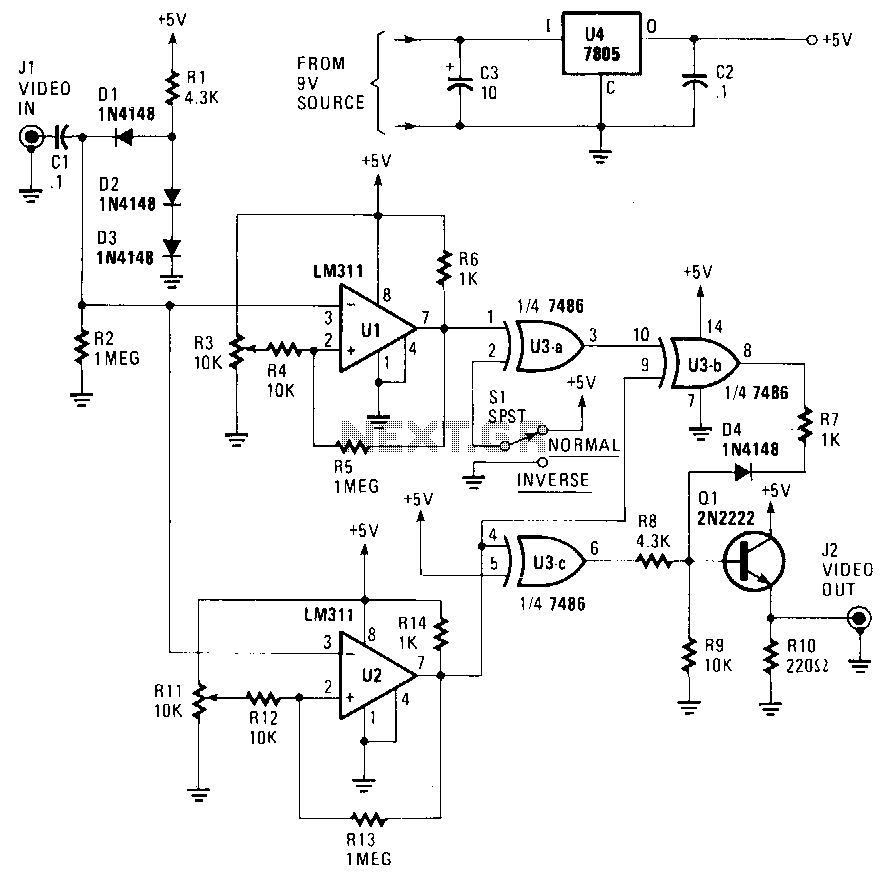
The circuit accepts a video signal, separates the sync pulses, inverts the video, and integrates new video with the existing sync pulses. The video signal is input through J1 and processed by a clamping circuit comprising C1, D1, D2, D3, R1, and R2. This clamping circuit ensures that all sync pulses align with the same DC voltage level. Once the video voltage is clamped, the trip points of the subsequent comparators can be adjusted using trimmer resistors R3 and R11. The resistors will not require readjustment. One comparator, U1, is set to change states based on variations in either video or sync-pulse levels, while the second comparator, U2, is configured to respond solely to changes in sync-pulse levels. The output from U1 generates a logic level signal ranging from 0 to +5 V, which includes both sync pulses and video. This composite signal is fed into an EXCLUSIVE-OR gate, U3a, where it can be inverted or not, depending on the position of switch NORM/REV S1. The output from pin 3 of U3a is subsequently directed to U3b, where the composite signal is merged with the sync-pulse-only output from U2. The EXCLUSIVE-OR function of U3b eliminates the sync pulses, resulting in an output that contains only the video signal. As the sync pulses are inverted when passing through U2, they require a final inversion before being combined with the video signal. This final inversion is executed by U3c, and the resulting output is combined with that of U3b through D4, R7, R5, and R9. The newly merged signal is buffered by emitter follower Q1 and transmitted to the external environment via J2. The circuit operates with a 9-to-12 V wall-mounted power supply, with the supply voltage being regulated down to 5 V by U4.
The circuit design incorporates several critical components to ensure proper functionality and signal integrity. The clamping circuit, utilizing capacitors and diodes, serves to stabilize the video signal and align sync pulses to a consistent reference level. This alignment is essential for accurate signal processing, particularly when dealing with varying input signal amplitudes.
The use of comparators, U1 and U2, allows for precise detection of signal transitions. U1 is responsible for monitoring both video and sync-pulse levels, enabling it to react to any changes in the overall signal. U2, on the other hand, focuses exclusively on the sync-pulse levels, ensuring that sync information is preserved while video content is processed.
The EXCLUSIVE-OR gates (U3a, U3b, and U3c) play a vital role in manipulating the signal. The configuration allows for selective inversion of the sync pulses and integration with the video signal. The choice of using an EXCLUSIVE-OR gate for this purpose is particularly effective, as it facilitates the cancellation of unwanted components (sync pulses) while allowing the desired video signal to pass through.
The output stage, buffered by Q1, ensures that the final video signal is robust enough for external interfacing, minimizing the effects of load variations on the output signal quality. The power supply regulation provided by U4 is crucial for maintaining stable operation of the circuit, ensuring that all components function within their specified voltage ranges.
Overall, this circuit effectively processes video signals by separating and managing sync pulses, providing a reliable output suitable for various applications in video signal processing.The circuit will accept a video signal, separate the sync pulses, invert the video, and add new video to the old sync pulses. The video signal is brought in through Jl and applied to a clamping circuit consisting of Cl, Dl, D2,D3, Rl, and R2.
The clamp circuit forces all of the sync pulses to align with the same de voltage level. With the video voltage clamped, the trip points of the comparators that follow can be set with trimmer resistors R3 and Rll. The resistors will not have to be readjusted. One comparator, Ul, is adjusted to change states with a change in either video or sync-pulse levels. The other comparator, U2, is adjusted to trip on changes of sync-pulse levels only. The output of Ul now consists of a logic level, 0 to +5 V, signal that contains both sync pulses and video.
The composite signal is coupled to an EXCLUSIVE-OR gate, U3a, where it is either inverted or not inverted, depending upon the position of switch NORM/REV Sl. The output, at pin 3 of U3a, is next sent to U3b. There the composite signal is combined with the sync-pulse only signal from U2. The EXCLUSIVE-OR action of U3b cancels out the sync pulses, leaving only video at the IC"s output. Since the sync pulses are inverted as they pass through U2, they must be inverted once more before being combined with the video signal.
That final inversion is performed bY U3c, and that device"s output is combined with that of U3b via D4, R7, RS, and R9. The newly combined signal is buffered bY emitterfollower Ql, and sentto the outside world via ]2. The circuit can be powered by a 9-to 12-V wall-mount power supply. The supply voltage is regulated down to 5 V bY U4. 🔗 External reference