
pid controller Building a temperature-controlled water bath
To create a temperature control system using a power thyristor, a basic understanding of the components and their interactions is essential. The system will require a temperature sensor, such as a thermistor or a thermocouple, to measure the water temperature. This sensor will provide an analog or digital signal based on the temperature reading.
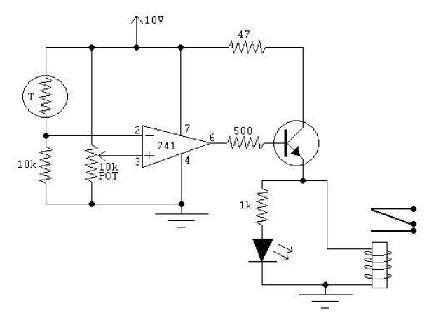
For an analog approach, a thermistor can be used, which varies its resistance with temperature. This resistance change can be converted to a voltage using a voltage divider circuit. The output voltage can then be fed into an operational amplifier configured as a comparator. The comparator will compare the voltage from the thermistor with a set reference voltage, which corresponds to the desired temperature. If the measured temperature falls below the set point, the output of the comparator will trigger the thyristor, allowing current to flow to the heating element. This configuration allows for continuous control of the heating element, adjusting the power as needed to maintain the desired temperature.
Alternatively, a digital circuit can be implemented using a microcontroller. The temperature sensor can be interfaced with the microcontroller, which will read the temperature data and execute a control algorithm. For example, a simple on/off control can be programmed, where the microcontroller turns the thyristor on when the temperature is below the set point and off when it reaches the desired temperature. This method allows for more flexibility and programmability, enabling the incorporation of features such as hysteresis to prevent rapid cycling of the heating element.
In both scenarios, the thyristor plays a crucial role in controlling the power delivered to the heating element. While an on/off regulation can work without the thyristor, using it allows for better control over the power output, especially in applications requiring precise temperature management. The choice between analog and digital solutions will depend on the complexity desired and the available components.
In summary, the system can be designed using either an analog or digital approach, utilizing a temperature sensor to monitor water temperature and a thyristor to control the heating element, all while staying within budget constraints.I have no experience whatsover with building controllers and have no clue on how to start. I don`t want to spend to much money on the project (< 100 ‚¬) thus money is an issue. The good thing is that I already have a power thyristor. My question is how I can best make the link between the sensor and the h eating element. I of course need to build/program a circuit that does this but do I make an analog or digital circuit I have a thyristor but is this really necessary or should an on/off regulation also work Don`t forget that I also should be able to define the water temperature. 🔗 External reference
Related Circuits
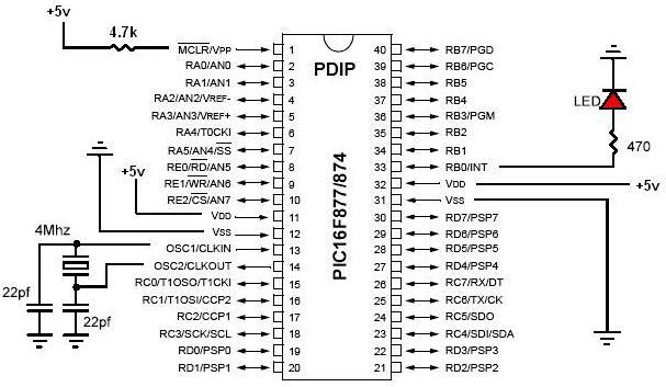
PIC development/testing board. This is a PCB design for a basic PIC16F877 development board. All that is required is a 4 MHz crystal, two 22 pF capacitors, and one 4.7 kΩ resistor. The PIC16F877 development board is designed to facilitate...
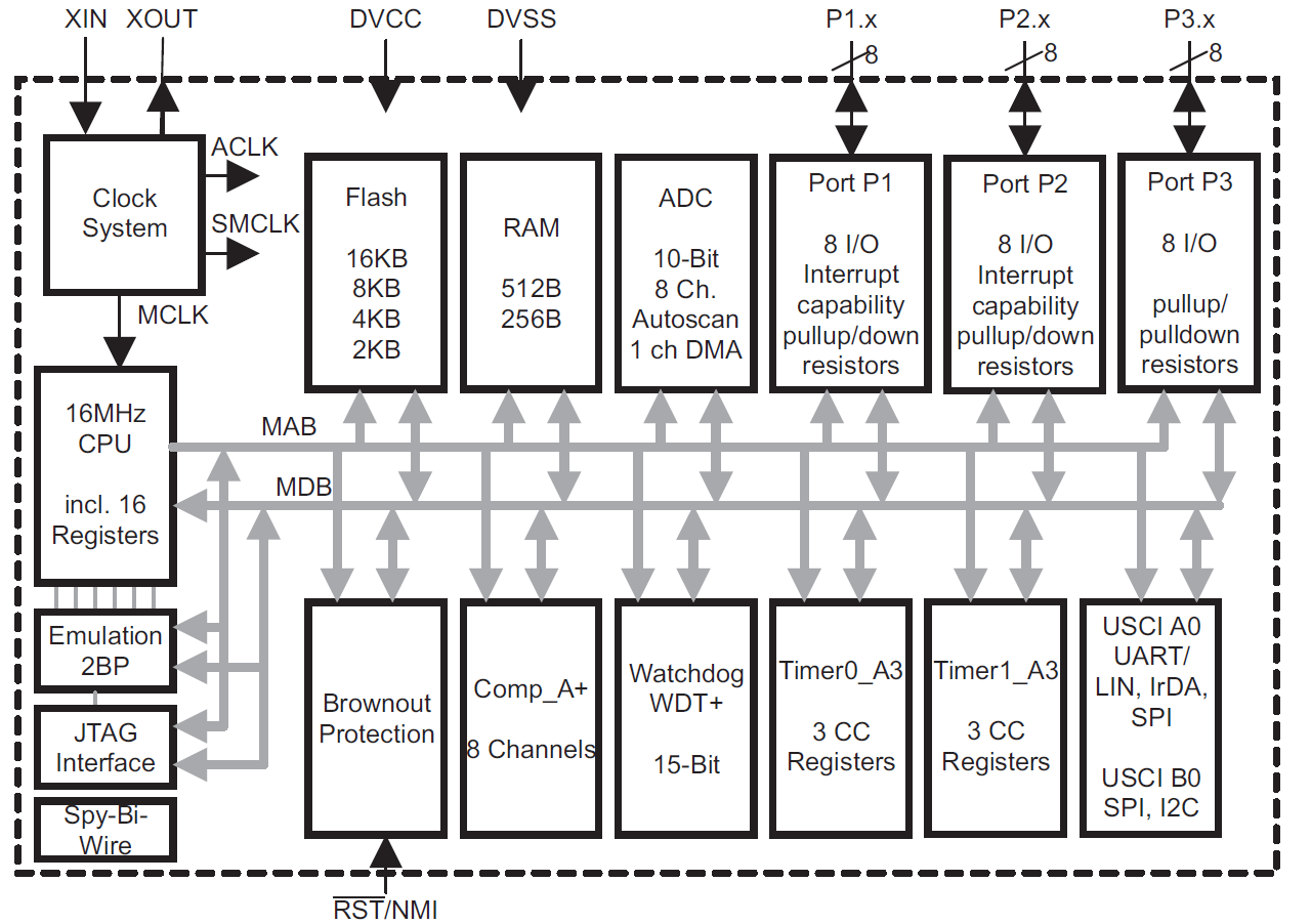
This module provides an overview of the MSP430 microcontroller, instructions on how to read its data sheet, and guidance on selecting the appropriate model for various applications. It is part of a textbook aimed at helping seniors choose Texas...
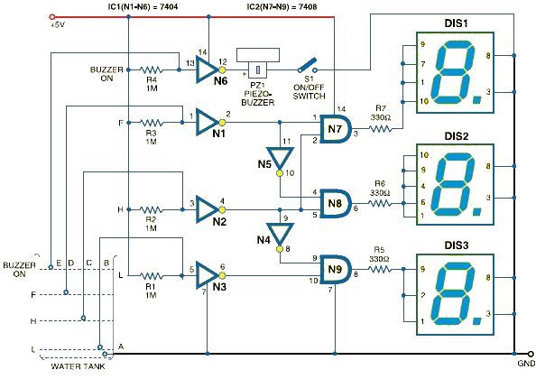
This schematic outlines a simple electronic circuit designed to indicate water levels using a 7-segment display. The circuit shows water levels by displaying 'L', 'H', and 'F' for low, half, and full levels, respectively. It is based on the...
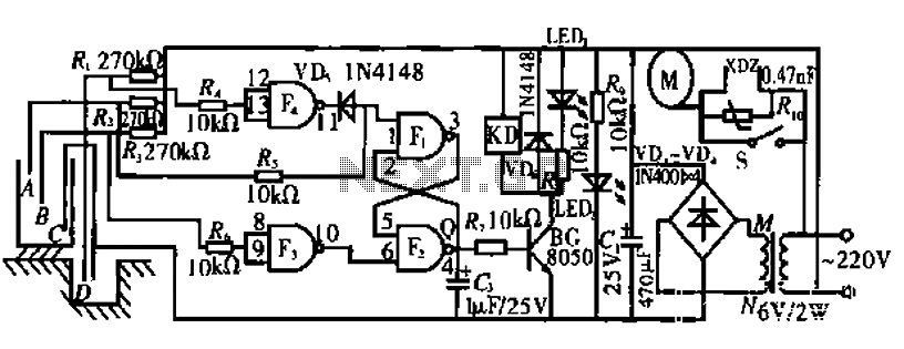
The circuit operates by monitoring the water level in a tank. When the water level falls below a specified point (F), the RS flip-flop (F2) is activated, producing a high Q output that energizes a relay to start the...
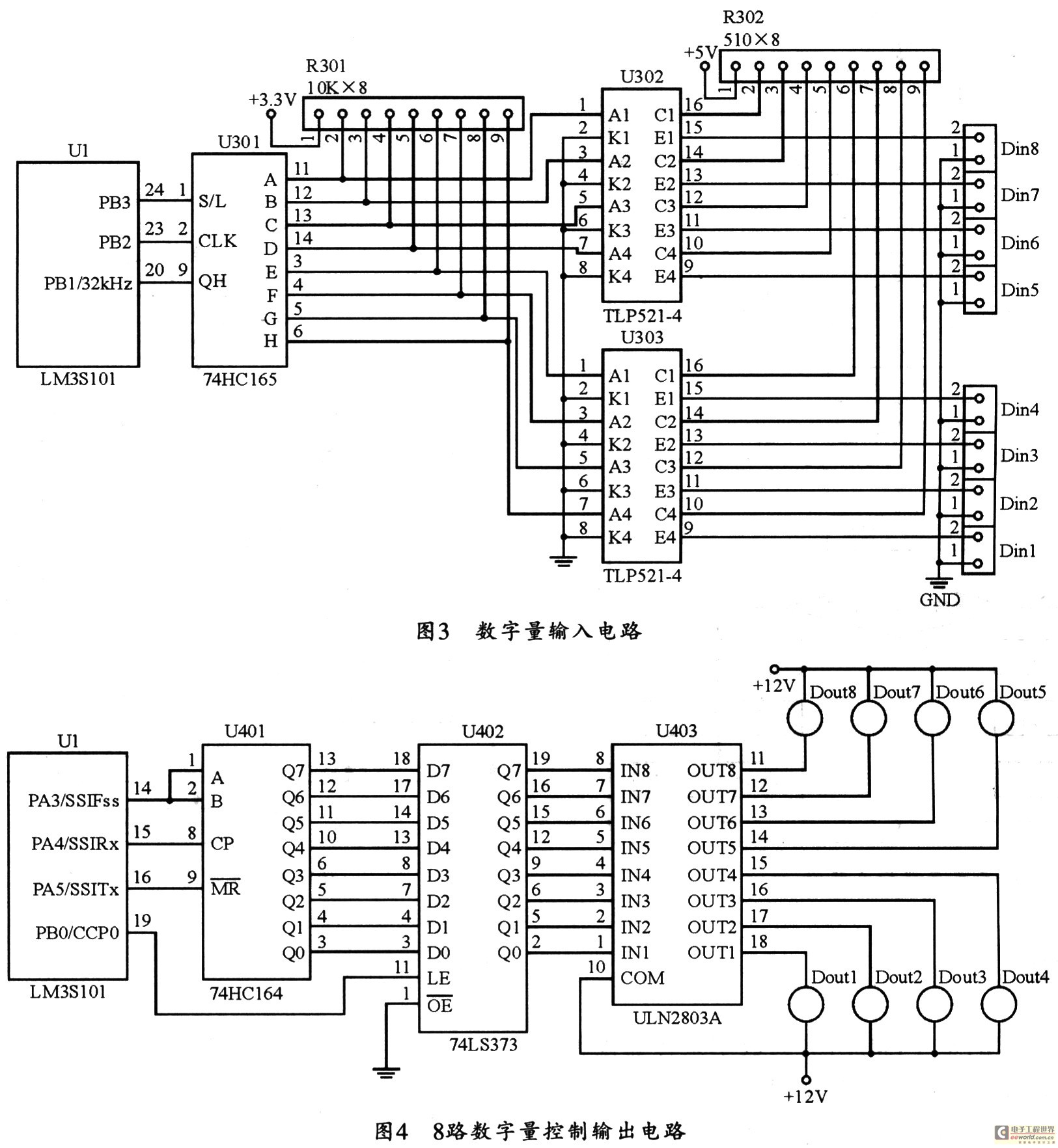
The figure utilizes a controller as the primary equipment for gathering and controlling digital data within an on-site monitoring system. The stability of on-site control operations is crucial to the overall system performance. Therefore, a simple and stable structure...
The circuit is constructed using two 555 timer integrated circuits, designated as U1 and U2. U1 is configured as a variable duty cycle oscillator with a fixed time period of approximately 0.1 seconds. The duty cycle can be adjusted...
Warning: include(partials/cookie-banner.php): Failed to open stream: Permission denied in /var/www/html/nextgr/view-circuit.php on line 713
Warning: include(): Failed opening 'partials/cookie-banner.php' for inclusion (include_path='.:/usr/share/php') in /var/www/html/nextgr/view-circuit.php on line 713