
Piezoelectric alarm rings clear as a bell

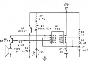
The circuit utilizes the 555 timer in an astable mode to generate a square wave output that controls the operation of the piezoelectric alarm. The timer's configuration allows for continuous oscillation, creating a rhythmic sound output. The low time (6.93 ms) corresponds to the duration of the initial bell strike, while the high time (236 ms) dictates how long the bell tone is sustained before it begins to decay.
The transistor switch (Q1) plays a crucial role in controlling the alarm. When the 555 timer outputs a low signal, Q1 is turned on, allowing current to flow through the piezoelectric alarm, producing sound. The charging of capacitor C3 during this phase helps ensure that the alarm is energized adequately. Upon transitioning to a high output from the timer, Q1 is turned off, which stops current flow to the alarm and allows the sound to decay as C3 discharges.
The timing components R1, R2, and C1 can be selected based on the desired sound characteristics. For instance, increasing R1 or R2 will extend the duration of the high time, resulting in a longer sustain phase. Alternatively, adjusting C1 will influence both the strike and sustain times. Capacitor C3's value can also be modified to create different decay rates for the sound output, allowing for customization of the alarm's auditory profile.
This circuit design is straightforward, cost-effective, and adaptable, making it suitable for various applications where a less abrasive sound output is preferred.A common piezoelectric alarm, such as the Murata (Smyrna, GA) PKB5-3A shown, has many valuable attributes. It is compact, lightweight, efficient and reliable. However, the loud, high-pitched sound output can be quite irritating in many applications. The simple and inexpensive circuit provided here transforms this obnoxious little buzzer into a ple asantsounding bell ( see the figure ). At the heart of the circuit is the popular 555 timer U1, which is configured as an astable multivibrator. The output low time is a short pulse that initiates the bell strike. The strike time is 0. 693 †” R2 †” C1. For the component values shown, the strike time is 6. 93 ms. The output high time is the sustain time during which the amplitude of the bell tone decays continuously.
The high time is 0. 693 †” (R1 + R2) †” (C1). For this circuit, the high time is 236 ms. When the output of U1 is low, the series transistor switch Q1 turns on through bias resistor R3 to energize the piezoelectric alarm AL1 and charge capacitor C3. When the output of U1 is high, Q1 is off and the output of AL1 decays until C3 is discharged. When C3 is discharged again, the cycle is repeated. The values of timing components R1, R2, and C1, along with decay capacitor C3, aren`t critical; various sound effects can be produced by experimenting with them.
🔗 External reference
Related Circuits
The simple bell circuit without IC. It includes a doorbell circuit that can produce different sounds using integrated circuits, transistors, and resistors. The circuit utilizes a coded trigger mechanism to differentiate between various visitors. When the button is pressed,...
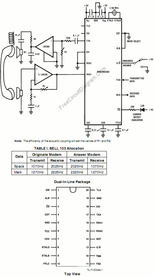
This circuit utilizes the MM74HC942, a single-chip low-speed modem that is compatible with the Bell 103 standard. The Bell 103 modem circuit operates at a baud rate of 300. The MM74HC942 is a versatile integrated circuit designed for low-speed data...
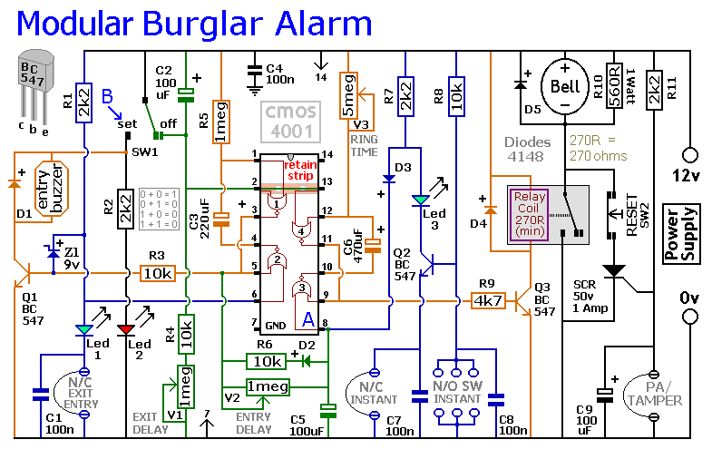
This circuit includes automatic exit and entry delays, as well as a timed bell cut-off feature. It supports both normally-closed and normally-open contacts, and incorporates a 24-hour personal attack/tamper zone. The use of expansion modules allows for the addition...
The following circuit illustrates a Sun Up Alarm Light Alarm Circuit Diagram. This circuit is based on the 555 Integrated Circuit (IC). Features include simplicity and cost-effectiveness. The Sun Up Alarm Light Alarm Circuit employs the 555 timer IC in...
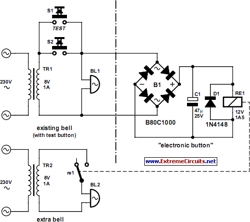
In some situations, a more complex approach is necessary, even when a simpler method is available. This scenario involves adding a second doorbell in parallel with an existing one. While this typically does not require additional electronic components, connecting...
This circuit dials a stored DTMF tone sequence from an EPROM when a control line is taken to 0 V. IC1 is a Schmitt trigger oscillator, operating at approximately 2 Hz. It clocks a 4024 binary counter. The outputs...
Warning: include(partials/cookie-banner.php): Failed to open stream: Permission denied in /var/www/html/nextgr/view-circuit.php on line 713
Warning: include(): Failed opening 'partials/cookie-banner.php' for inclusion (include_path='.:/usr/share/php') in /var/www/html/nextgr/view-circuit.php on line 713