
Piezoelectric Sound
A piezoelectric sounder, particularly the self-drive type, operates based on the principle of piezoelectricity, where mechanical stress applied to piezoelectric materials generates an electrical charge. In this configuration, the piezoelectric diaphragm is the primary element that vibrates to produce sound waves. The feedback electrode enhances the efficiency of the oscillation by providing a mechanism for the diaphragm to self-excite, amplifying the sound output.
The external drive circuit typically consists of a transistor that acts as a switch, controlling the current flow through the piezoelectric diaphragm. The three resistors in the circuit help set the biasing conditions and determine the oscillation frequency. The simplicity of this design allows for easy integration into various electronic systems.
When designing applications that utilize piezoelectric sounders, it is crucial to consider the resonant frequency of the diaphragm, as this frequency will yield the highest sound pressure output. The ability of the sounder to operate effectively at various frequencies allows for versatility in application, including alert signals, notifications, and musical tones.
The adjustment of the duty cycle is an important technique for managing sound pressure levels without altering the voltage supply. By varying the duty cycle—essentially the proportion of time the signal is on versus off—the average power delivered to the sounder can be increased, thus enhancing the perceived loudness. This method is particularly useful in battery-operated devices where power conservation is essential.
In summary, the piezoelectric sounder (external drive type) is a highly efficient component suitable for a wide range of audio applications. Its low current consumption, versatility in frequency response, and the ability to manipulate sound pressure through duty cycle adjustments make it a preferred choice in modern electronic designs. Proper evaluation of the sound pressure characteristics across different frequencies is recommended to optimize performance in specific applications.In contrast, a piezoelectric sounder (self drive type) consists of only a piezoelectric diaphragm with a feedback electrode. It is used in combination with an external drive circuit. The drive circuit for both of the above is a simple circuit consisting of one transistor and three resistors.
When a DC voltage V is applied to the drive circuit, the oscillation conditions in the circuit are satisfied in the vicinity of the resonant frequency. As a result, the piezoelectric diaphragm is driven at the oscillation frequency, causing it to emit a sound. Regarding the drive circuit for a piezoelectric sounder (self drive type), we set a standard circuit for each product.
For details, please refer to our catalog. In contrast to an electromagnetic buzzer which is driven by a current flowing through a built-in electromagnet coil, a piezoelectric sound component is driven by a voltage applied to piezoelectric ceramic. Consequently, it features much lower current consumption than that of an electromagnetic buzzer. The current consumption (excluding that of the peripheral circuit) by a piezoelectric sounder (external drive type) can be calculated simply from the theoretical equation below.
When the charging and discharging times of a piezoelectric sounder (external drive type) are significantly smaller than the length of one period of the input signal, the average value of the current which flows into the piezoelectric sounder (external drive type) during a half period can be calculated from the following equation. The average value of the current flowing through the piezoelectric sounder (external excited type), calculated using the above equation for each part No.
, is shown in the table below. Provided that you use the product within the range of the maximum input voltage specified for each product, there is no need to take account of the electrical polarity. Is there any problem with using a Piezoelectric Sounder (External Drive Type) at a frequency other than that used to obtain the specified sound pressure level A piezoelectric sounder (external drive type) is designed to produce sound at a stable sound pressure when it is driven at the frequency used to obtain the specified sound pressure, however it will also produce sound at other frequencies as well.
Consequently, it can produce not only a single sound but also melodies and other complex sounds, enabling it to be used in such applications as operation confirmation sounds, alarms, melodies, and pseudo sounds. However, there are cases in which the sound pressure level becomes very small depending upon the drive frequency, although this will also depend upon the frequency characteristics of sound pressure level of each product, so check and evaluate the product before using it.
Can a Piezoelectric Sounder (External Drive Type) intended to be driven at 4 kHz in order to obtain the specified sound pressure level is driven at 2 kHz, and the sound pressure increased as well A piezoelectric sounder (external drive type) is a voltage-driven type. In order to increase the sound pressure, it is necessary to raise the input voltage. However, generally it is not easy to increase the input voltage to the drive circuit. Accordingly, the sound pressure can be raised by changing the duty ratio of the input voltage without changing the input voltage.
(Regarding the duty ratio, refer to Fig. 1. ) When a piezoelectric sounder intended to be driven at 4 kHz in order to obtain the specified sound pressure is to be driven at 2 kHz, change the duty ratio of the input signal from 50% to 25%. Taking our piezoelectric sounder PKM13EPYH4002-B0 as an example, this will cause the sound pressure to rise by approximately 10 dB.
(Refer to Fig. 2 and Fig. 3. ) This result depends upon the frequency characteristics of sound pressure level of the piezoelectric sounder, so the value of the increase in sound pressure will differ according to the type of 🔗 External reference
Related Circuits
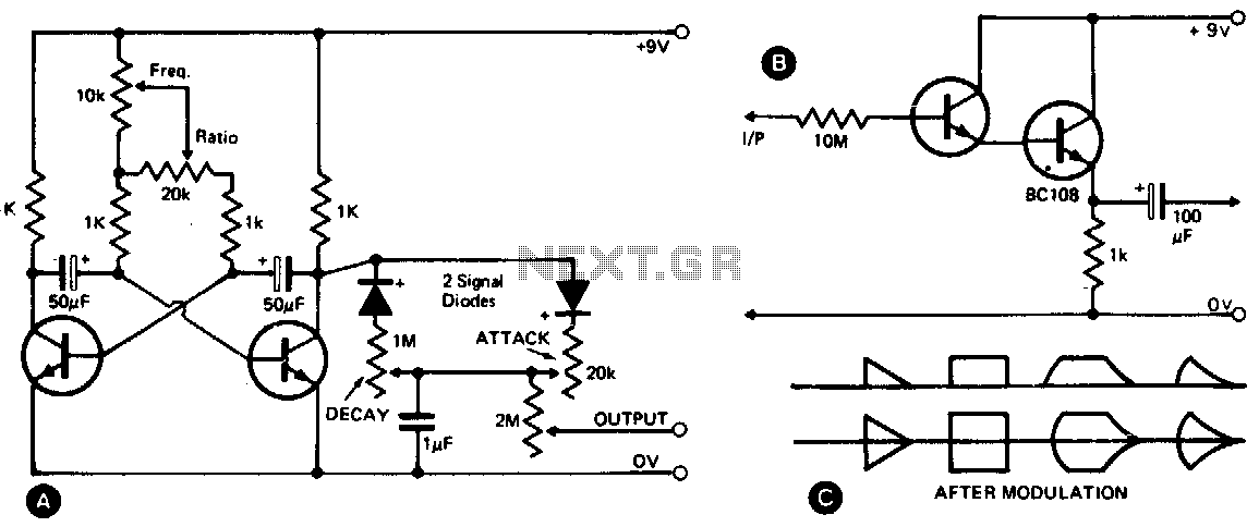
This waveshape generator functions as a slow-running oscillator with adjustable attack and decay times. It features a variable amplitude output, which is high impedance and can be controlled through a 2M potentiometer. Additionally, an add-on circuit is illustrated in...
Implementing tactile (haptic) feedback in consumer electronic devices enhances the user experience by providing a sense of touch in user interface design. It represents the latest major interface innovation in smartphones and other portable consumer electronic devices. Various haptic...
This sound level measuring device circuit can be used to control the intensity of a sound recording in the field of a disco. It has five measurement ranges between 70 and 120 dB, with a measurement accuracy of 0.5...
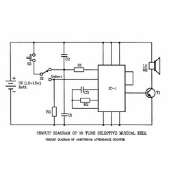
The core of the circuit is an IC4822, referred to as IC1. The IC4822 is a programmed ROM that produces 16 musical tunes upon being triggered. Its main features include an integrated tone generator, rhythm generator, modulator, oscillator, frequency...
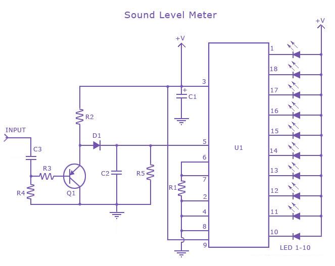
This is a single-chip sound level meter that can be used to display the sound level of an amplifier or simply the sound level from a microphone. The core component of the circuit is the IC LM3915 Audio Level...
This sound level meter serves as an effective one-chip replacement for standard analog meters. It is entirely solid-state, ensuring durability and longevity. The circuit is built around the LM3915 audio level integrated circuit (IC) and requires only a minimal...