
pipe descaler schematics
An initial astable oscillator, based on a traditional 555 timer (IC3), operates at approximately 10 kHz when only capacitor C6 is active, meaning transistor T1 is in a blocked state. T1 is controlled by another astable oscillator, utilizing IC1, which operates at about 1 Hz. When T1 is activated by IC1, capacitor C4 is effectively placed in parallel with C6, reducing the frequency generated by IC3 to around 5 kHz. To generate high amplitude signals, the power supply employs a mid-point transformer in an unconventional manner, utilizing simple half-wave rectification. The first half of the secondary winding delivers 15 VAC, which, after rectification, filtering, and regulation by IC2, provides a stable 12VDC current to power the oscillators. The entire secondary winding yields approximately 40VDC after rectification, which is used to energize coils L1 and L2, wound around the pipe systems targeted by the device.
Following IC3, a high-voltage transistor (T2, such as a BF457 or equivalent) modulates this high voltage at frequencies of 5 or 10 kHz, depending on the state of IC1. An LED (D3) illuminates to indicate that power is present. Coils L1 and L2 are simple inductors made from insulated flexible wire, each consisting of approximately ten turns. These coils must be wound around the pipes carrying the water to be treated, with a spacing of about ten centimeters between them. Importantly, neither the material of the pipe system nor its diameter should significantly impact the device's efficiency. Interestingly, the coils have one end exposed, which may seem surprising. However, the primary aim of this project is to enable the construction of a device similar to those available in stores, allowing for personal experimentation and testing of its efficacy.For many years now, magnetic (or electromagnetic) water descaler devices have been showing up on the shelves of Home Improvement and other DIY stores all over Europe. Despite the numerous studies completed on that subject, by manufacturers as well as by various consumer associations, none have been able to conclude on the efficiency of commercial
pipe descalers in a decisive manner. Since electronic devices of this type are relatively expensive (especially when we discover what they are made of!), we decided to offer this project to our readers. For the price of a few tens of pounds, you will be able to evaluate the state of your own faucets, pots, and other pipes.
The device we`re offering as a project is identical to top-of-the-line items found on sale; in other words, it includes the bi-frequency option because it seemed that would be the best way to fight lime scale deposits. An initial astable oscillator, based on a traditional 555, labeled IC3, functions at around 10 kHz when the only capacitor C6 is operating; in other words, when T1 is blocked.
The latter is controlled by another astable oscillator, based on IC1 this time, but which functions at about 1 Hz. When T1 is turned on by IC1, capacitor C4 is effectively in parallel with C6 which divides the frequency produced by IC3 by two, i.
e. to about 5 kHz. In order to have high amplitude signals, the power supply operates with a mid-point transformer utilized in an unconventional way, with simple half-wave rectification. The first half of the secondary delivers 15 VAC which, after being rectified, filtered and regulated by IC2, supply stable current of 12VDC to supply power to the oscillators.
The entire secondary makes it possible to have available, after rectification, approximately 40VDC which is used to supply power to coils L1 and L2, wound around the pipe systems on which the assembly will work. To do that, IC3 is followed by high-voltage transistor T2 (a BF457 or equivalent) which chops this high voltage to 5 or 10 kHz frequency depending on the state of IC1.
LED D3 lights up to signal that the power supply is present. Coils L1 and L2 are simple inductors made from insulated flexible wire, with about ten windings each. They have to be wound around the pipes carrying the water to be treated` and are spaced about ten centimeters from each other.
Neither the material of the pipe system, nor its diameter, should have any influence on the efficiency of the device. Paradoxically, these coils have one end in the air, which may surprise you as much as us but we indicated at the beginning of this article, that our goal with this project is not to explain the principle but rather to allow you to make the same device as those sold in stores, so that you can perform your own tests.
🔗 External reference
Related Circuits

To quickly determine if a remote control transmitter is functioning properly, a remote control detector can be utilized. If the remote control transmitter is operational, the detector will emit an audible alarm signal. This detector is capable of assessing...
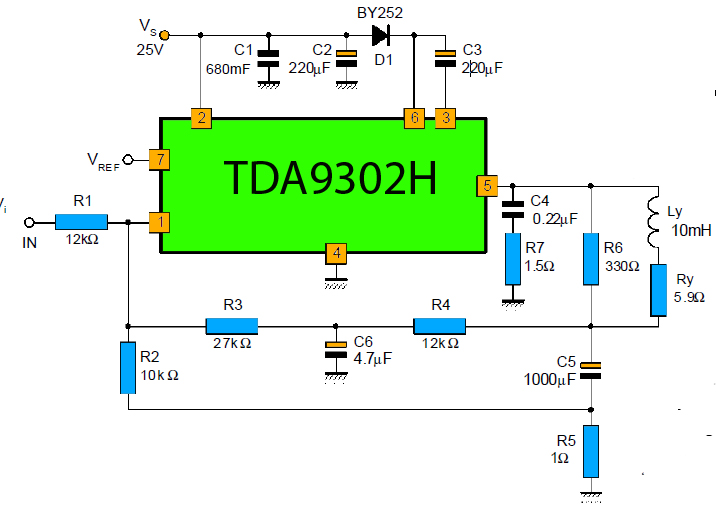
The TDA9302H is a monolithic integrated circuit housed in a HEPTAWATTTM package. It functions as a high-efficiency power amplifier designed for direct drive vertical deflection coils in television yokes. This component is suitable for use in both color and...
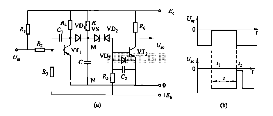
The circuit features a delay action with an instantaneous reset control mechanism. It is categorized into three types: a conducting pipe rechargeable delay circuit, a tube cut-off control rechargeable delay circuit, and a discharge-type delay circuit. In the conducting...
Hello everyone, my name is Mike, and I come from a small country called New Zealand. I am currently planning to build a 6L6 push-pull stereo power amplifier and preamplifier. The project involves designing a 6L6 push-pull stereo power amplifier,...

The third Eagle layout of the program counter has been completed, presenting a clearer design compared to the previous iterations, which were cluttered with intersecting wires, making it difficult to discern connections. This diagram is intended to facilitate understanding...
In all instances where Darlington transistors serve as output devices, it is crucial for the sensing transistor (Q4) to maintain close thermal contact with the output transistors. Consequently, a TO126-case transistor type was selected for ease of mounting onto...