
PlayPICG
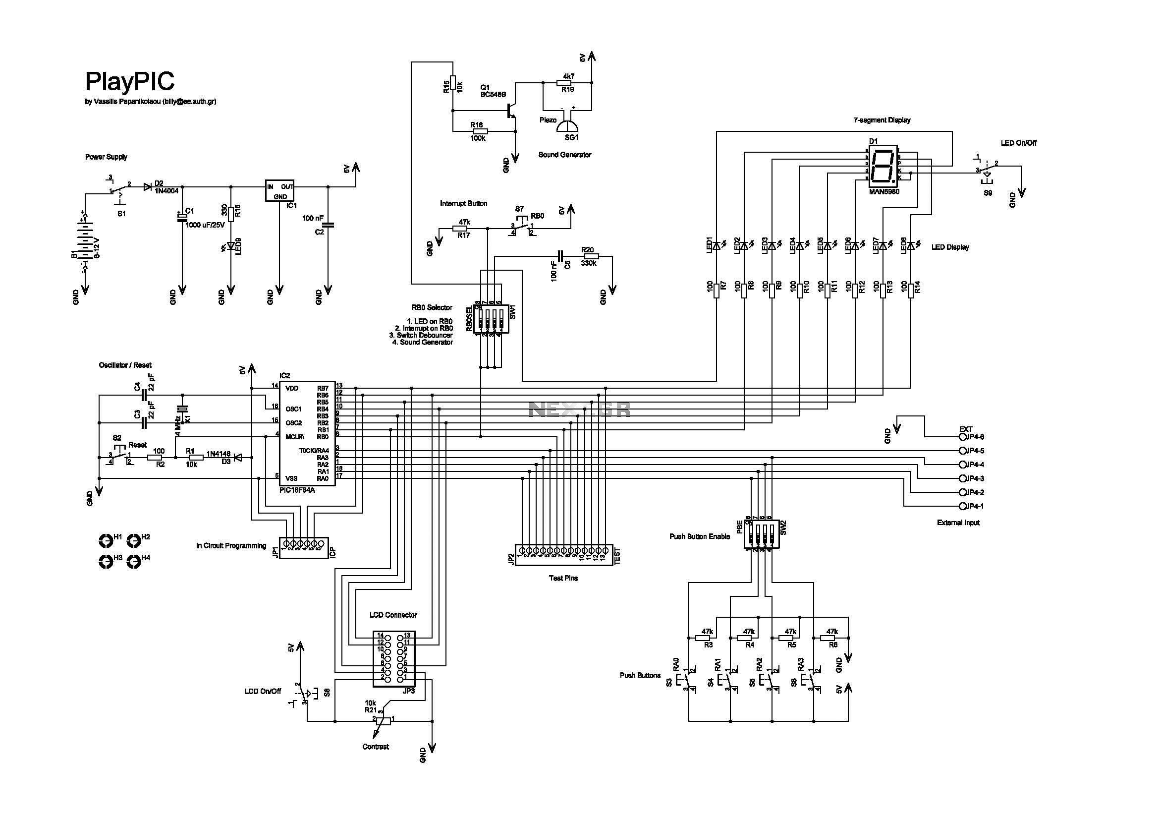
This is a new design of a tutorial board based on the popular PIC16F84A microcontroller. It features eight single LEDs, a 7-segment display, an LCD display, and five push buttons. It is an ideal solution for beginners to take their first programming steps in the world of microcontrollers. Equipped with an in-circuit programming (ICP) header, it can be easily reprogrammed without unplugging the microcontroller each time, provided that the programmer also supports this feature (like OziPicG). The 7-segment display is always connected to the individual LEDs. Its seven segments correspond to LED2 through LED8 (RB1 to RB7) and the decimal point corresponds to LED1 (RB0). This correspondence enables the 7-segment display to work in conjunction with the interrupt switch S7, which is connected to RB0. JP4 is a 6-screw external input connector for RA0-RA4. When used, the corresponding input switches S3-S6 must be turned off by SW2. The last screw is for ground. The top photo shows the in-circuit programming procedure with the help of an appropriate programmer (like OziPic`er) which features an ICP header. In order for the procedure to work correctly, the LCD module must be disconnected from its socket during programming.
The tutorial board is designed to facilitate learning and experimentation with the PIC16F84A microcontroller, which is known for its simplicity and effectiveness in educational settings. The board incorporates eight individual LEDs that serve both as indicators and as part of the 7-segment display functionality. The 7-segment display uses seven segments to represent numerical values, with LED2 to LED8 controlling the segments and LED1 representing the decimal point. This setup allows for straightforward visual feedback during programming exercises and debugging.
The incorporation of an in-circuit programming (ICP) header allows users to reprogram the microcontroller without the hassle of physically removing it from the board. This feature is particularly advantageous for beginners who may need to make frequent changes to their code. The board's design ensures that the programming process is streamlined, as long as a compatible programmer is used.
The board also includes an LCD display, which can provide additional information and user interaction capabilities. However, it is essential to note that during the programming phase, the LCD module must be disconnected to avoid interference with the programming process. This requirement emphasizes the importance of careful setup and understanding of the hardware when working with microcontrollers.
The external input connector (JP4) facilitates the connection of external devices or sensors, allowing for further experimentation and learning. The requirement to disable the corresponding input switches (S3-S6) through SW2 when using the external connector ensures that the board maintains proper functionality and prevents conflicts between internal and external inputs.
Overall, this tutorial board is a comprehensive platform for beginners to gain hands-on experience with microcontroller programming and hardware interfacing, providing a solid foundation for further exploration in electronics and embedded systems.This is a new design of a tutorial board based on the popular PIC16F84A microcontroller. It features eight single leds, a 7-segment display, an LCD display and five push buttons. It is an ideal solution for the beginner to take his/her first programming steps in the world of microcontrollers. Having an in-circuit-programming (ICP) header, it can b e easily reprogrammed without unplugging the microcontroller each time, provided that the programmer also supports this feature (like OziPicG ™er). - The 7-segment display is always connected to the individual leds. Its seven segments correspond to LED2 to LED8 (RB1 to RB7) and the decimal dot to LED1 (RB0). This correspondence enables the 7-segment display to work together with the interrupt switch S7, which is connected to RB0.
- JP4 is an 6-screw external input connector for RA0-RA4. When used, the corresponding input switches S3-S6 must be turned off by SW2. Last screw is ground. The top photo shows the in-circuit-programming procedure with the help of an appropriate programmer (like OziPic`er) which features an ICP header. In order for the procedure to work correctly, the LCD module has to be disconnected from its socket during programming.
🔗 External reference