
PlayPICs
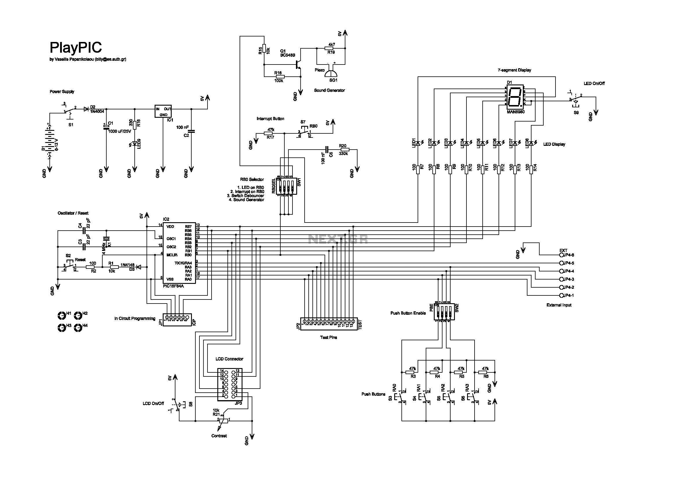
This is a new design of a tutorial board based on the popular PIC16F84A microcontroller. It features eight single LEDs, a 7-segment display, an LCD display, and five push buttons. It is an ideal solution for beginners to take their first programming steps in the world of microcontrollers. With an in-circuit programming (ICP) header, it can be easily reprogrammed without unplugging the microcontroller each time, provided that the programmer also supports this feature (like OziPic'er). The 7-segment display is always connected to the individual LEDs. Its seven segments correspond to LED2 to LED8 (RB1 to RB7) and the decimal dot to LED1 (RB0). This correspondence enables the 7-segment display to work together with the interrupt switch S7, which is connected to RB0. JP4 is a 6-screw external input connector for RA0-RA4. When used, the corresponding input switches S3-S6 must be turned off by SW2. The last screw is ground. The top photo shows the in-circuit programming procedure with the help of an appropriate programmer (like OziPic'er) which features an ICP header. In order for the procedure to work correctly, the LCD module has to be disconnected from its socket during programming.
The tutorial board designed around the PIC16F84A microcontroller serves as an educational platform for novice users to familiarize themselves with microcontroller programming and interfacing. The board incorporates multiple components to facilitate learning, including eight single LEDs that can be individually controlled, a 7-segment display for numeric output, an LCD display for more complex information presentation, and five push buttons for user input.
The in-circuit programming (ICP) capability is a significant feature, allowing users to reprogram the microcontroller without the need for physical disconnection. This feature is particularly beneficial for iterative development and testing, streamlining the learning process. The compatibility with programmers such as OziPic'er enhances its usability, ensuring that learners can easily update their code.
The 7-segment display's connection to the individual LEDs provides a practical demonstration of how microcontroller outputs can be utilized to drive visual indicators. Each segment of the display corresponds to specific pins on the microcontroller (RB1 to RB7), while the decimal point is linked to RB0. This setup allows for real-time feedback based on user inputs or programmed conditions, particularly when combined with the interrupt switch S7.
The board also includes a JP4 connector with six screw terminals for external inputs on RA0 to RA4, expanding the board's capabilities for more advanced projects. It is essential to deactivate the corresponding input switches (S3-S6) via switch SW2 when utilizing the external connector to prevent conflicts in input readings. The last terminal serves as a ground connection, ensuring a complete circuit for reliable operation.
During the programming process, it is critical to disconnect the LCD module from its socket. This precaution is necessary to avoid interference that could disrupt the programming of the microcontroller. Overall, this tutorial board is a comprehensive resource for beginners, providing a hands-on approach to learning microcontroller programming and interfacing.This is a new design of a tutorial board based on the popular PIC16F84A microcontroller. It features eight single leds, a 7-segment display, an LCD display and five push buttons. It is an ideal solution for the beginner to take his/her first programming steps in the world of microcontrollers. Having an in-circuit-programming (ICP) header, it can b e easily reprogrammed without unplugging the microcontroller each time, provided that the programmer also supports this feature (like OziPic ’er). - The 7-segment display is always connected to the individual leds. Its seven segments correspond to LED2 to LED8 (RB1 to RB7) and the decimal dot to LED1 (RB0). This correspondence enables the 7-segment display to work together with the interrupt switch S7, which is connected to RB0.
- JP4 is an 6-screw external input connector for RA0-RA4. When used, the corresponding input switches S3-S6 must be turned off by SW2. Last screw is ground. The top photo shows the in-circuit-programming procedure with the help of an appropriate programmer (like OziPic`er) which features an ICP header. In order for the procedure to work correctly, the LCD module has to be disconnected from its socket during programming.
🔗 External reference