
Pocket-sized geiger counter
The described circuit operates on a 6.75 V mercury battery, which is a compact power source suitable for low-power applications. The counter is designed to measure pulse rates, with the output displayed on a 1 mA analog meter and an associated audible signal. The use of a regulated 900 V supply is critical for maintaining the performance of the counter tube, ensuring consistent operation and accuracy in pulse detection.
The multivibrator circuit, constructed using a differential power amplifier (IC2), is responsible for generating the necessary high-voltage pulses to drive a step-up transformer. This transformer increases the voltage to the required 900 V for the counter tube. The comparator circuit (IC1) plays a vital role in controlling the duty cycle of the multivibrator, which in turn stabilizes the output voltage, ensuring that the counter tube operates efficiently without fluctuations that could affect measurement accuracy.
The regulated supply is designed to be energy-efficient, drawing less than 2 mA, which is particularly advantageous for battery-operated devices, extending their operational lifespan. The one-shot multivibrator (IC3) produces output pulses of fixed width and amplitude, which are essential for providing a reliable pulse rate to the meter. The average current through the meter correlates directly with the pulse rate output from the counter tube, facilitating straightforward interpretation of the measurements.
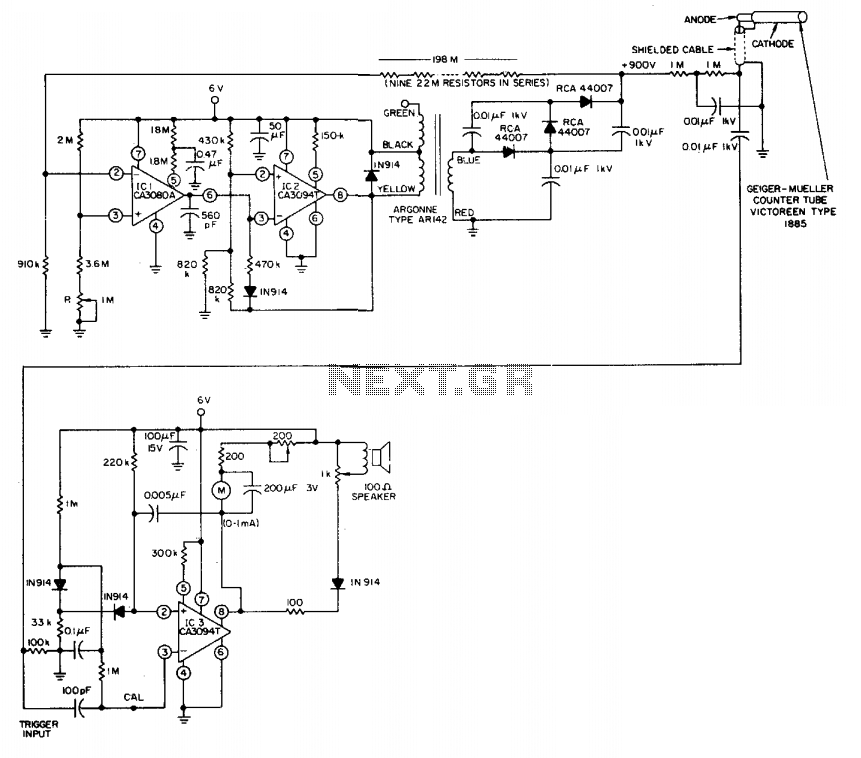
At full-scale deflection, the meter reads 1 mA, which corresponds to a pulse rate of 5000 counts per minute or approximately 83.3 pulses per second. For ease of use and calibration, a specific checkpoint is marked on the meter scale to indicate a pulse rate of 3600 parts per million (ppm), equating to 60 pulses per second. This feature enhances the usability of the device by allowing users to quickly reference standard measurement rates during operation.A single 6.75 V mercury battery powers the counter, which features a 1 mA count-rate meter as well as an aural output. A regulated 900 V supply provides stable operation of the counter tube. A multivibrator, built around a differential power amplifier IC2, drives the step-up transformer. Comparator IC1 varies the multivibrator duty cycle to provide a constant 900 V. The entire regulated supply draws less than 2 mA. A one-shot multivibrator, built with IC3, provides output pulses that have constant width and amplitude.
Thus the average current through the meter is directly proportional to the pulse-rate output from the counter tube. And the constant-width pulses also drive the speaker. Full-scale meter deflection (1 mA) represents 5000 counts/min, or 83.3 pulses/s. A convenient calibration checkpoint can be provided on the meter scale for 3600 ppm (60 pulses/s.) 🔗 External reference
Related Circuits
The frequency counter is designed to measure the number of cycles per second of an incoming signal. A counting device is necessary for this purpose, and in electronic circuits, counter integrated circuits (ICs) are available for counting input pulses....

The schematic for this project is visually acceptable, although it is not the most refined layout for a schematic. The basic flow progresses from left to right, starting with the state machine, followed by the 555 timers, then the...
With this counter you can count laps for example (in conjunction with the Simple light trap). The circuit uses two TTL ICs 74LSxx the series. The left IC is a decimaalteller. The input pulses 14 are counted and converted...
This circuit measures the distance covered during a walk. The hardware is located in a small box that can be slipped into a pants pocket. The display is designed such that the leftmost display, D2 (the most significant digit),...
The 7208 seven-stage decimal counter can be utilized as a frequency counter. It features latch and multiplexing functions, along with direct digital driving circuitry and display driving circuitry. The output frequency of the 7207 IC 6.5536 MHz crystal oscillator...
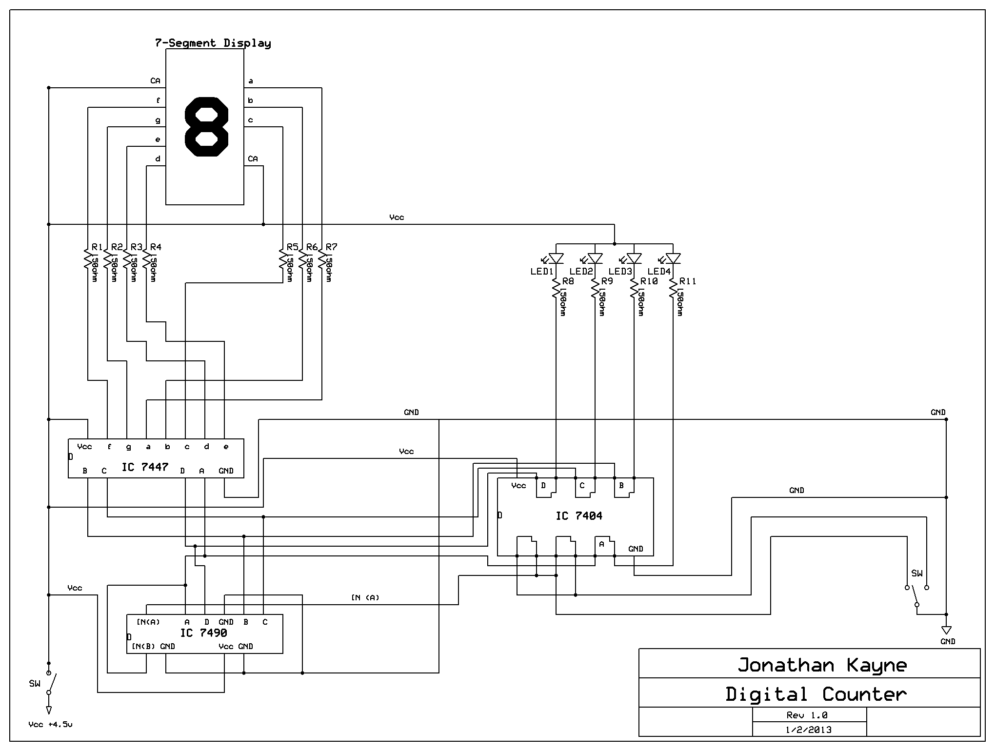
The Digital Counter Circuit is an electronic project that converts digital numbers (0-9) to binary (0-1). For those interested in understanding binary code, a PowerPoint presentation on the topic is available. Below are the parts list, schematic, and additional...