
Positive-regulator-with-pnp-boost
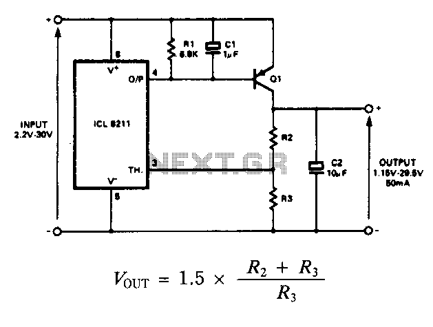
The IC8211 serves as the voltage reference and regulator amplifier, with Q1 functioning as the series pass transistor. Resistor R1 defines the output current of the IC8211, while capacitors C1 and C2 ensure loop stability and help suppress the feedthrough of input transients to the output supply. Resistors R2 and R3 are responsible for determining the output voltage. The values of R2 and R3 are selected to provide a small amount of standing current in Q1, which enhances the stability margin of the circuit. In scenarios where precise output voltage settings are necessary, either R2 or R3 can be made adjustable. If R2 is adjusted, the output voltage will change linearly with the rotation of the potentiometer's shaft; however, if the potentiometer wiper disconnects, the output voltage will increase. Therefore, it is generally preferable to make R3 adjustable to ensure fail-safe operation.
The IC8211 is a precision voltage reference and regulator amplifier integrated circuit designed to deliver stable output voltage under varying load conditions. It incorporates a series pass transistor, Q1, which regulates the output current defined by resistor R1. The stability of the output voltage is further enhanced by capacitors C1 and C2, which mitigate the effects of input voltage transients and contribute to the overall loop stability of the circuit.
Resistors R2 and R3 play a critical role in setting the output voltage. The selection of their values not only determines the output voltage level but also ensures that a small standing current flows through Q1, thereby increasing the circuit's stability margin. This design consideration is essential for applications requiring high reliability and precision.
In applications where the output voltage must be adjustable, either R2 or R3 can be configured as a variable resistor. Making R2 adjustable allows for linear variation of the output voltage in accordance with the adjustment of the potentiometer's shaft angle. However, a potential drawback arises if the wiper of the potentiometer becomes disconnected, leading to an unintended rise in output voltage. To mitigate this risk, it is advisable to configure R3 as the adjustable component, as this arrangement provides a fail-safe mechanism, ensuring that the output voltage remains within a safe operating range even in the event of a potentiometer failure.
Overall, the described circuit configuration using the IC8211, along with the specified components, offers a robust solution for applications requiring precise voltage regulation and stability, while also allowing for user-adjustable output voltage settings in a fail-safe manner.The IC8211 provides the voltage reference and regulator amplifier, while Ql is the series pass transistor. Rl defines the output current of the IC8211, while Cl and C2 provide loop stability and also act to suppress feedthrough of input transients to the output supply.
R2 and R3 determine the output voltage. In addition, the values of R2 and R3 are chosen to provide a small amount of standing current in Ql, which gives additional stability margin to the circuit. Where accurate setting of the output voltage is required, either R2 or R3 can be made adjustable. If R2 is made adjustable, the output voltage will vary linearly with the shaft angle; however, if the potentiometer wiper was to open the circuit, the output voltage would rise. In general, therefore, it is better to make R3 adjustable, since this gives fail-safe operation. 🔗 External reference