
Positive-triggered-touch-circuit
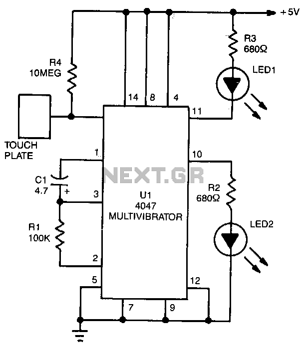
LED1 and LED2 indicators activate and stay illuminated each time the circuit is triggered. During the timing cycle, the Q output at pin 10 of U1 becomes positive when the Q output at pin 11 turns negative. The two LEDs can be omitted, allowing the Q and Q outputs at pins 10 and 11, respectively, to be utilized to trigger another circuit.
The circuit described is likely a timing circuit utilizing a flip-flop or timer IC, such as the 555 timer or a similar device, where the Q (output high) and Q' (output low) states are used to manage the operation of connected components. In this setup, LED1 and LED2 serve as visual indicators of the circuit's state, providing feedback to the user when the circuit is activated.
Upon triggering the circuit, the timing mechanism initiates a cycle during which the Q output at pin 10 transitions to a high state (positive voltage), while the Q output at pin 11 transitions to a low state (ground or near zero voltage). This behavior indicates that the circuit is functioning correctly and is capable of responding to external inputs or conditions.
The option to remove the LEDs and utilize the Q outputs for further circuit integration enhances the flexibility of the design. By connecting external components to these outputs, such as relays, other logic circuits, or additional timers, the base circuit can be expanded to perform more complex tasks. This adaptability is essential in applications where visual indicators are not necessary, allowing for a more compact and efficient design.
For practical implementation, it is crucial to ensure that the connected components can handle the voltage and current levels present at the Q outputs. Proper considerations for load impedance and power ratings must be taken into account to prevent damage to the circuit or connected devices. Additionally, decoupling capacitors may be employed near the IC to stabilize power supply fluctuations and enhance overall circuit reliability.LED1 and LED2 indicators turn on and remain on, each time the circuit is triggered. During the timing cycle, U1 "s Q output at pin 10 becomes positive when the Q output at pin 11 becomes negative. The two LEDs can be removed and the Q and Q outputs at pins 10 and 11, respectively, can be used LED2 to trigger some other circuit. 🔗 External reference
Warning: include(partials/cookie-banner.php): Failed to open stream: Permission denied in /var/www/html/nextgr/view-circuit.php on line 713
Warning: include(): Failed opening 'partials/cookie-banner.php' for inclusion (include_path='.:/usr/share/php') in /var/www/html/nextgr/view-circuit.php on line 713