
Power-converter
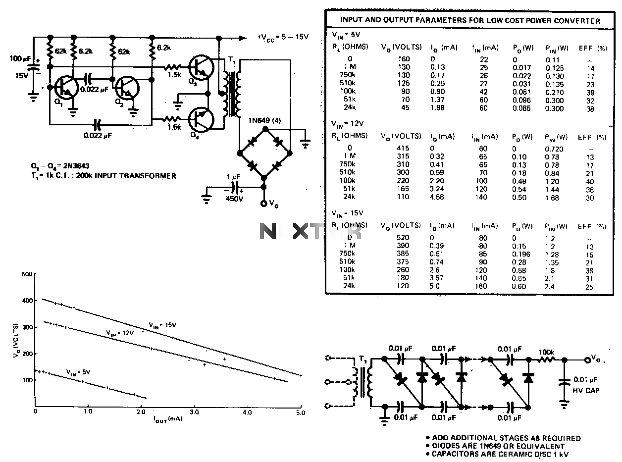
This circuit consists of an astable multivibrator driving a push-pull pair of transistors into the transformer primary. The multivibrator frequency should equal around 1 or 2 kHz. For higher DC voltages, voltage multipliers on the secondary circuit have been used successfully to generate 10 kV from a 40-stage multiplier like the one shown.
The described circuit employs an astable multivibrator, a type of oscillator that produces a continuous square wave output. This square wave is utilized to drive a push-pull configuration of transistors, which are crucial for efficiently switching the current through the primary winding of a transformer. The frequency of oscillation is set to approximately 1 kHz to 2 kHz, which is suitable for many applications requiring rapid switching.
In the push-pull arrangement, two transistors operate alternately, allowing for a more efficient transfer of energy into the transformer. This configuration helps minimize the losses typically associated with single-ended designs, as it balances the load across the transistors and reduces heat generation.
The transformer is integral to the circuit, stepping up the voltage from the primary side to the secondary side. For applications requiring high DC voltages, such as 10 kV, a voltage multiplier circuit is implemented on the secondary side. This circuit typically consists of a series of capacitors and diodes arranged in a configuration that allows for the multiplication of the input voltage. A 40-stage multiplier, for instance, can effectively achieve significant voltage amplification, making it suitable for applications such as high-voltage power supplies or electrostatic generators.
The design considerations for this circuit include ensuring that the transistors can handle the required current and voltage levels, selecting appropriate transformer specifications, and ensuring that the voltage multiplier stages are properly rated to handle the high voltages generated. Additionally, attention must be paid to the layout and insulation to prevent arcing and ensure safe operation at elevated voltages.This circuit consists of an astable multivibrator driving a push-pull pair of transistors into the transformer primary. The multivibrator frequency should~equal around 1 or 2kHz. For higher de voltages, voltage multipliers on the secondary circuit have been used successfully to generate 10 k V from a 40~stage multiplier like the one shown. 🔗 External reference