Power over Ethernet
1. Definition and Basic Concept of PoE
Definition and Basic Concept of PoE
Power over Ethernet (PoE) is a technology that enables the simultaneous transmission of electrical power and data over standard Ethernet cabling, eliminating the need for separate power supplies. The IEEE 802.3af (2003), 802.3at (Type 2, 2009), and 802.3bt (Type 3/4, 2018) standards define the specifications for PoE, including voltage levels, power budgets, and negotiation protocols.
Electrical Characteristics
PoE operates using a nominal voltage of 48V DC, applied differentially across the Ethernet cable pairs. The power sourcing equipment (PSE) delivers power using either:
- Alternative A (Mode A): Power over data pairs (pins 1-2 and 3-6)
- Alternative B (Mode B): Power over spare pairs (pins 4-5 and 7-8)
The maximum current per pair is limited to 350mA for IEEE 802.3af/at and 600mA for 802.3bt, with total system power budgets of 15.4W, 30W, and up to 90W respectively.
where \( P_{loss} \) accounts for resistive losses in the cable, calculated as:
Power Classification
The PSE performs a detection and classification sequence to determine the powered device's (PD) requirements:
- Detection: 2.7V-10V signature applied to measure PD resistance (25kΩ ± 1.25kΩ)
- Classification: 15.5V-20.5V applied to determine power class (0-8)
| Class | Max Power (W) | Standard |
|---|---|---|
| 0 | 15.4 | 802.3af |
| 4 | 30 | 802.3at |
| 8 | 90 | 802.3bt |
Physical Layer Implementation
Modern PoE systems use phantom power techniques to maintain data integrity while superimposing DC power. The PSE includes:
- Isolation transformers with center-tapped windings
- Common-mode chokes for EMI suppression
- Active bridge rectifiers in PDs for polarity independence
The Ethernet signal remains unaffected due to the high-pass filtering characteristics of the data transformers, while the DC power passes through the center taps.
1.2 Historical Development and Standards
Early Innovations and Pre-Standard Implementations
The concept of transmitting both power and data over Ethernet cables emerged in the late 1990s, driven by the need to simplify deployments of networked devices like VoIP phones and wireless access points. Early proprietary solutions, such as Cisco's Inline Power (1999) and 3Com's Power over Ethernet, delivered up to 6W using spare pairs in Category 5 cables. These implementations lacked interoperability but demonstrated feasibility, using a 48V DC supply with resistive detection to avoid damaging non-PoE devices.
IEEE 802.3af (2003): The First Standard
The IEEE 802.3af standard formalized PoE with a maximum delivered power of 15.4W (12.95W at the device). It introduced a two-phase handshake: detection (2.7–10.1V probing to identify compatible devices) and classification (14.5–20.5V signaling to determine power requirements). Power sourcing equipment (PSE) could deliver energy via Mode A (data pairs 1-2 and 3-6) or Mode B (spare pairs 4-5 and 7-8). The standard mandated galvanic isolation (1500V AC) for safety.
IEEE 802.3at (2009): PoE+
Increased demand for higher-power devices led to PoE+, which doubled available power to 30W (25.5W at load). Key enhancements included:
- Extended classification (Class 4 devices drawing 12.95–25.5W)
- Support for two-event physical layer classification
- Mandatory 10GBASE-T compatibility
Voltage tolerance was tightened to ±1V (50–57V), reducing losses in cabling runs up to 100m.
IEEE 802.3bt (2018): 4PPoE
The 802.3bt standard introduced four-pair power delivery (4PPoE), enabling two power profiles:
- Type 3: 60W (51W delivered) via all four pairs
- Type 4: 100W (71.3W delivered) with improved efficiency (94% PSE)
New autoclass mechanisms reduced energy waste by dynamically adjusting power allocation. The standard also defined harmonic limits to minimize electromagnetic interference (EMI) in high-density deployments.
Alternative Standards and Extensions
Proprietary implementations like UPoE (Cisco) and HDBaseT pushed beyond IEEE limits, delivering up to 95W for specialized applications. The IEC 60950-23 safety standard addressed arc-fault prevention in high-power PoE systems, requiring current monitoring at 10kHz resolution.
1.3 Key Advantages and Use Cases
for advanced readers:Power and Data Integration
Power over Ethernet (PoE) eliminates the need for separate power cabling by delivering both electrical power and data over a single Ethernet cable. The IEEE 802.3af/at/bt standards define power delivery up to 90 W (Type 4), with voltage ranges between 44–57 V DC. Power sourcing equipment (PSE) negotiates power requirements with powered devices (PDs) using the Link Layer Discovery Protocol (LLDP), ensuring optimal power allocation.
Where Rcable depends on conductor gauge (typically 0.20 Ω/m for Cat5e). This integration reduces installation costs by up to 50% compared to traditional wiring.
Key Advantages
- Simplified Infrastructure: Single-cable deployment reduces clutter and eliminates AC outlet dependencies.
- Scalability: PoE switches support dynamic power budgeting (up to 71.3 W per port under IEEE 802.3bt).
- Safety: PSEs implement fault detection (25kΩ signature resistance check) and overcurrent protection.
- Energy Efficiency: Centralized power management enables granular control, reducing idle consumption by 30–40%.
High-Power Applications
Modern PoE++ (Type 3/4) supports demanding loads:
- PTZ Cameras: 25–50 W for high-resolution imaging and mechanical actuation.
- Wi-Fi 6/6E Access Points: 30–60 W for multi-radio MIMO configurations.
- Thin Clients: 40–70 W for desktop virtualization terminals.
Industrial Use Cases
PoE’s galvanic isolation (1500 V AC withstand voltage) makes it ideal for harsh environments:
- Factory Automation: Powering IP67-rated sensors (e.g., 4–20 mA transmitters) with intrinsic safety barriers.
- Building Management: HVAC controls and occupancy sensors leveraging Power Sourcing Equipment (PSE) redundancy.
Emerging Applications
PoE is expanding into novel domains:
- LiDAR Arrays: 60–90 W for automotive-grade point-cloud generation.
- Edge AI: Powering GPU-accelerated inference devices (e.g., NVIDIA Jetson via PoE++ splitters).
2. IEEE 802.3af (PoE)
IEEE 802.3af (PoE)
Power Delivery Specifications
The IEEE 802.3af standard, ratified in 2003, defines Power over Ethernet (PoE) delivery over standard Ethernet cabling (Category 3 or higher). It specifies a nominal 48V DC supply with a maximum power output of 15.4W per port at the Power Sourcing Equipment (PSE). Accounting for cable losses, the minimum guaranteed power at the Powered Device (PD) is 12.95W.
The voltage range is strictly regulated:
Four-Pair Power Distribution
802.3af utilizes two alternative power delivery methods:
- Alternative A (Mode A): Power over data pairs (pins 1-2, 3-6) in 10/100BASE-T implementations
- Alternative B (Mode B): Power over spare pairs (pins 4-5, 7-8)
The standard mandates that PSEs must support both modes, while PDs need only support one. The power distribution follows:
Detection and Classification
Before applying power, the PSE performs a three-phase handshake:
- Detection: Measures input impedance (25kΩ signature)
- Classification: Determines power requirements (0-4 classes)
- Startup: Applies power with controlled inrush current
The classification current levels are:
| Class | Current (mA) | Max Power (W) |
|---|---|---|
| 0 | 0-5 | 15.4 |
| 1 | 9-12 | 4.0 |
| 2 | 17-20 | 7.0 |
| 3 | 26-30 | 15.4 |
| 4 | 36-44 | Reserved |
Electrical Characteristics
The standard imposes strict requirements on PSE output characteristics:
- Output ripple ≤ 5% of nominal voltage
- Current limit of 350mA per pair (400mA during startup)
- Isolation voltage ≥ 1500V AC between PD and PSE
The maximum cable resistance is calculated based on worst-case scenarios:
Practical Implementation Challenges
Real-world deployments must account for:
- Non-ideal cable characteristics (skin effect, temperature variations)
- Voltage drop across long cable runs (100m maximum)
- Power dissipation in magnetics and connectors
- Transient protection against induced surges
The power efficiency η of a PoE link can be expressed as:
Advanced Power Management
Modern implementations incorporate dynamic power adjustment techniques:
- Load-dependent voltage scaling
- Adaptive current limiting
- Real-time power budgeting
The power management algorithm typically follows:
2.2 IEEE 802.3at (PoE+)
Power Delivery Enhancements
The IEEE 802.3at standard, ratified in 2009, extends the capabilities of the original 802.3af (PoE) by doubling the available power per port to 25.5 W under worst-case conditions. This is achieved through:
- Increased voltage range: 50–57 V (vs. 44–57 V in 802.3af)
- Maximum current: 600 mA per mode (compared to 350 mA in 802.3af)
- Two-event physical layer classification
Four-Pair Power Delivery
While 802.3af utilized only two pairs for power transmission, PoE+ introduced optional four-pair powering (Alternative B), enabling higher efficiency and reduced cable heating. The power distribution follows:
where Rwire accounts for the resistance per pair (typically 20 Ω/100m for Cat5e).
Link Layer Discovery Protocol (LLDP)
PoE+ mandates LLDP for dynamic power negotiation, allowing devices to communicate their exact power requirements (in 0.1 W increments) through Type-Length-Value (TLV) fields. The power budget allocation follows:
Thermal Management
To mitigate cable heating at higher currents, 802.3at requires:
- Temperature monitoring via resistive thermal devices (RTDs)
- Derating curves for ambient temperatures >45°C
- Current imbalance tolerance of <10% between pairs
Application Examples
PoE+ enables power-hungry devices such as:
- Pan-tilt-zoom (PTZ) IP cameras with heaters
- Thin clients with multi-core processors
- 802.11ac wireless access points
IEEE 802.3bt (PoE++)
The IEEE 802.3bt standard, ratified in 2018, represents the third generation of Power over Ethernet (PoE) technology, delivering substantially higher power levels than its predecessors while maintaining backward compatibility. It introduces two new power types (Type 3 and Type 4) and implements advanced power management features through the Automatic Classification mechanism.
Power Delivery Architecture
802.3bt utilizes all four pairs of the Ethernet cable (compared to two pairs in 802.3af/at), enabling power delivery modes of up to 90W (Type 4) at the Powered Device (PD). The standard defines:
- Type 3 (PoE++): 51W delivered power (60W PSE output)
- Type 4 (High-Power PoE): 71.3W delivered power (90W PSE output)
where η represents the system efficiency (typically 0.85-0.95), VPSE is the PSE output voltage (44-57V), and Ploss accounts for cable dissipation.
Four-Pair Power Distribution
The standard specifies three four-pair powering schemes:
- Alternative A: Pairs 1-2 and 3-6 carry power and data simultaneously
- Alternative B: Dedicated power on pairs 4-5 and 7-8
- Alternative C: All four pairs carry power (data only on pairs 1-2 and 3-6)
This multi-pair approach reduces current density per conductor, minimizing resistive losses. For a 90W load at 50V:
Automatic Classification Enhancements
The 802.3bt standard introduces a five-event physical layer classification process:
- Initial detection (2.7V-10.1V signature)
- Class 0-8 identification
- Extended power capability negotiation
- Maintenance classification
- Final power confirmation
The classification current signature now includes 9 distinct levels (Class 0-8), enabling precise power budgeting. The classification resistance Rclass follows:
where Vclass = 15.5V-20.5V and Iclass ranges from 5mA to 40mA depending on class.
Efficiency Improvements
802.3bt incorporates several techniques to improve energy efficiency:
- Active Mode Power Management: Dynamic power adjustment based on PD needs
- Low Power Idle: Reduced power during inactive periods
- Optimized Voltage Regulation: 3.3V, 5V, and 12V auxiliary rails
The standard achieves typical efficiency of 94% at full load through synchronous rectification and advanced switching topologies in the PD interface.
Real-World Implementation Considerations
Deploying 802.3bt systems requires attention to:
- Cable heating effects (I2R losses)
- Return loss specifications for maintained signal integrity
- Isolation requirements between power and data paths
- Thermal management of PSE components
The maximum channel length remains 100m, but power delivery must account for temperature-dependent resistance:
where α is the copper temperature coefficient (0.00393/°C) and R20°C is the DC resistance at 20°C.
Power Classification and Levels
IEEE 802.3af (PoE) Power Classes
The IEEE 802.3af standard defines four power classes (0–3) for Power Sourcing Equipment (PSE) and Powered Devices (PD). These classes determine the maximum power allocated during the classification phase, ensuring efficient power management. The classification occurs before full power delivery, allowing the PSE to allocate only the necessary power.
- Class 0: Default classification, up to 15.4W at PSE (12.95W at PD).
- Class 1: Guarantees 4.0W at PD (PSE allocates 4.5W).
- Class 2: Guarantees 7.0W at PD (PSE allocates 7.5W).
- Class 3: Guarantees 15.4W at PD (PSE allocates 15.4W).
The classification process involves applying a voltage between 14.5V and 20.5V and measuring the current drawn by the PD. The resulting current determines the power class.
IEEE 802.3at (PoE+) Enhancements
The IEEE 802.3at standard introduced Class 4, supporting higher power delivery up to 25.5W at the PSE (25W at PD). This was achieved by increasing the current limit to 600mA per pair (compared to 350mA in 802.3af). PoE+ also supports two-event classification (Layer 2 classification) for finer power negotiation.
IEEE 802.3bt (4PPoE) Power Expansion
The IEEE 802.3bt standard further extends power delivery by introducing:
- Class 5: Up to 40W at PD (45W at PSE).
- Class 6: Up to 51W at PD (60W at PSE).
- Class 7: Up to 62W at PD (75W at PSE).
- Class 8: Up to 71.3W at PD (90W at PSE).
802.3bt utilizes all four pairs of the Ethernet cable, significantly improving efficiency and reducing resistive losses. The standard also introduces Autoclass, allowing PDs to dynamically request power adjustments.
Power Dissipation and Efficiency Considerations
Cable resistance (Rcable) plays a critical role in PoE efficiency. For long cable runs, power dissipation increases quadratically with current, as shown by Joule heating:
Higher-voltage PoE standards (e.g., 802.3bt) mitigate losses by reducing current for the same power level. For example, delivering 60W at 50V requires only 1.2A, whereas 48V PoE+ requires ~1.25A, and 24V legacy systems would need 2.5A.
Real-World Implications
In enterprise networks, proper power classification ensures optimal power budgeting. A switch with a 370W power budget might support:
- 24 × Class 3 (802.3af) devices, or
- 12 × Class 4 (802.3at) devices, or
- 6 × Class 6 (802.3bt) devices.
Advanced PSEs use dynamic power allocation to adjust power delivery based on real-time PD demands, improving energy efficiency in large deployments.
3. Power Sourcing Equipment (PSE)
Power Sourcing Equipment (PSE)
Power Sourcing Equipment (PSE) is the active component in a Power over Ethernet (PoE) system responsible for supplying DC power to connected Powered Devices (PDs). PSEs are classified into two types based on their placement in the network: endspan (integrated into Ethernet switches) and midspan (standalone injectors between switches and PDs).
PSE Power Classification
The IEEE 802.3af/at/bt standards define four power classes for PSEs, determined during the PD detection phase via a resistive signature:
- Class 0: 15.4W max (802.3af)
- Class 1: 4.0W max
- Class 2: 7.0W max
- Class 3: 15.4W max
- Class 4: 30W max (802.3at Type 2)
- Class 5-8: Up to 90W (802.3bt Type 3/4)
PSE Detection and Power Delivery
The PSE initiates a three-phase handshake:
- Detection: Measures PD input resistance (25kΩ signature)
- Classification: Determines power requirements via current pulses
- Power-up: Applies 44-57V DC with inrush current limiting
Where ρ is copper resistivity (1.68×10⁻⁸ Ω·m), L is cable length, and A is conductor cross-section.
Advanced PSE Features
Modern PSEs implement:
- MPS (Maintain Power Signature): Continuous PD monitoring via 10mA current pulses
- LLDP (Layer 2 Discovery): Dynamic power negotiation via Ethernet frames
- Per-port power budgeting: Allocates power based on real-time demand
Thermal Considerations
High-power PSEs (802.3bt) require thermal modeling to prevent overheating:
Where θja is junction-to-ambient thermal resistance and η is conversion efficiency (typically 85-92%).
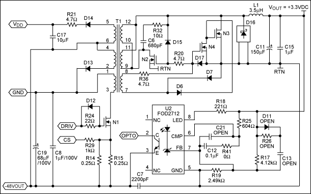
3.2 Powered Devices (PD)
Functional Architecture of a Powered Device
A Powered Device (PD) in a PoE system consists of several critical subsystems that enable power extraction and regulation from the Ethernet cable while maintaining data integrity. The primary functional blocks include:
- Signature and Classification Circuit – Identifies the PD as IEEE 802.3af/at/bt compliant and negotiates power class.
- Isolation and Protection Circuitry – Safeguards against overvoltage, inrush current, and reverse polarity.
- DC-DC Converter – Steps down the input voltage (typically 48V) to usable levels (e.g., 3.3V, 5V, 12V).
- Data Coupling Transformers – Maintains signal integrity while isolating high-frequency data from DC power.
Power Negotiation and Classification
During the detection phase, the Power Sourcing Equipment (PSE) applies a low-voltage probe (2.7V–10.1V) to measure the PD's signature resistance (25kΩ ±1%). If valid, the PSE proceeds to classification by applying a higher voltage (15.5V–20.5V) and measuring current draw to determine power requirements:
where \( V_{class} \) is the PSE's classification voltage, \( V_{PD} \) is the PD's internal voltage drop, and \( R_{class} \) is the classification resistor. IEEE 802.3bt extended classification to eight levels (up to 90W), introducing dual-event classification for higher power negotiation.
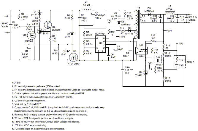
DC-DC Conversion Efficiency
The PD's DC-DC converter must efficiently handle wide input voltage ranges (37V–57V for 802.3at). The conversion efficiency \( \eta \) is given by:
Modern synchronous buck converters achieve >90% efficiency through zero-voltage switching (ZVS) and adaptive dead-time control. Losses are dominated by MOSFET conduction (\( I^2R_{DS(on)}} \)) and switching losses (\( \frac{1}{2} C_{oss} V_{in}^2 f_{sw}} \)).
Inrush Current Management
When a PD connects, bulk capacitors must charge without tripping the PSE's current limit (400mA for 802.3af). The inrush current is controlled by:
where \( C \) is the total input capacitance (limited to 180μF for 802.3at). Active inrush controllers use soft-start techniques with timed MOSFET activation to stay within the 50ms power-on window.
Real-World Design Considerations
- Thermal Management – High-power PDs (≥30W) require heatsinking or forced airflow to dissipate 3–10W of converter losses.
- EMI Compliance – Common-mode chokes and π-filters suppress high-frequency noise from switching converters.
- Fault Protection – UL 60950-1 mandates redundant overcurrent protection (e.g., fuses + current-limiting ICs).
3.2 Powered Devices (PD)
Functional Architecture of a Powered Device
A Powered Device (PD) in a PoE system consists of several critical subsystems that enable power extraction and regulation from the Ethernet cable while maintaining data integrity. The primary functional blocks include:
- Signature and Classification Circuit – Identifies the PD as IEEE 802.3af/at/bt compliant and negotiates power class.
- Isolation and Protection Circuitry – Safeguards against overvoltage, inrush current, and reverse polarity.
- DC-DC Converter – Steps down the input voltage (typically 48V) to usable levels (e.g., 3.3V, 5V, 12V).
- Data Coupling Transformers – Maintains signal integrity while isolating high-frequency data from DC power.
Power Negotiation and Classification
During the detection phase, the Power Sourcing Equipment (PSE) applies a low-voltage probe (2.7V–10.1V) to measure the PD's signature resistance (25kΩ ±1%). If valid, the PSE proceeds to classification by applying a higher voltage (15.5V–20.5V) and measuring current draw to determine power requirements:
where \( V_{class} \) is the PSE's classification voltage, \( V_{PD} \) is the PD's internal voltage drop, and \( R_{class} \) is the classification resistor. IEEE 802.3bt extended classification to eight levels (up to 90W), introducing dual-event classification for higher power negotiation.
DC-DC Conversion Efficiency
The PD's DC-DC converter must efficiently handle wide input voltage ranges (37V–57V for 802.3at). The conversion efficiency \( \eta \) is given by:
Modern synchronous buck converters achieve >90% efficiency through zero-voltage switching (ZVS) and adaptive dead-time control. Losses are dominated by MOSFET conduction (\( I^2R_{DS(on)}} \)) and switching losses (\( \frac{1}{2} C_{oss} V_{in}^2 f_{sw}} \)).
Inrush Current Management
When a PD connects, bulk capacitors must charge without tripping the PSE's current limit (400mA for 802.3af). The inrush current is controlled by:
where \( C \) is the total input capacitance (limited to 180μF for 802.3at). Active inrush controllers use soft-start techniques with timed MOSFET activation to stay within the 50ms power-on window.
Real-World Design Considerations
- Thermal Management – High-power PDs (≥30W) require heatsinking or forced airflow to dissipate 3–10W of converter losses.
- EMI Compliance – Common-mode chokes and π-filters suppress high-frequency noise from switching converters.
- Fault Protection – UL 60950-1 mandates redundant overcurrent protection (e.g., fuses + current-limiting ICs).
Midspan vs. Endspan PoE
Power over Ethernet (PoE) implementations can be broadly categorized into midspan and endspan architectures, differing primarily in their placement within the network topology and their method of power injection. Understanding their distinctions is critical for optimizing power delivery, minimizing signal degradation, and ensuring compatibility with existing infrastructure.
Endspan PoE (PoE Switch)
Endspan devices, commonly referred to as PoE switches, integrate power sourcing equipment (PSE) directly into the network switch. These switches inject DC power onto the Ethernet cable alongside data signals, eliminating the need for additional power injectors. The IEEE 802.3af/at/bt standards define the power delivery mechanisms, with modern switches supporting up to 90W (Type 4) per port.
The voltage and current relationships in an endspan configuration follow:
where Vport is the switch output voltage, Iload the current drawn by the powered device (PD), Rcable the cable resistance, and VPD the operating voltage at the PD. Endspan switches typically employ Alternative A (power over data pairs 1,2 and 3,6) or Alternative B (power over spare pairs 4,5 and 7,8), with most modern implementations defaulting to Alternative A for compatibility.
Midspan PoE (Power Injector)
Midspan devices, or power injectors, are standalone units inserted between a non-PoE switch and the PD. They add power to the Ethernet cable without modifying the existing network infrastructure. Midspans are particularly useful in retrofitting legacy networks, as they allow PoE deployment without replacing switches.
Power injection in midspans follows a different constraint:
where Pinjector is the midspan output power, PPD the power received by the PD, and Pcable_loss the dissipated power due to cable resistance. Midspans exclusively use Alternative B injection, as they cannot interfere with the data pairs already carrying signals from the non-PoE switch.
Comparative Analysis
The choice between midspan and endspan architectures involves trade-offs in cost, flexibility, and performance:
- Signal Integrity: Endspan switches often exhibit superior noise immunity due to integrated power management ICs that minimize crosstalk between power and data lines. Midspans may introduce additional jitter if not properly shielded.
- Scalability: Endspan solutions scale more efficiently in large deployments, as each port can be individually controlled via protocols like LLDP. Midspans require manual per-port configuration.
- Retrofit Compatibility: Midspans are the only viable option for legacy networks with non-PoE switches, though they increase cable clutter.
- Power Budget: High-power applications (e.g., 802.3bt Type 3/4) favor endspan switches, which typically offer higher per-port budgets (60W–90W) compared to midspans (usually capped at 30W for Type 1/2).
Practical Deployment Considerations
In real-world installations, cable resistance becomes a dominant factor. For CAT5e/CAT6 cables, the maximum permissible voltage drop (ΔV) at full load current (I) over distance (L) can be approximated by:
where Rper_meter is typically 0.1Ω/m for 24 AWG conductors. This drop must not exceed 7V for 802.3af/at compliance, limiting midspan deployments to ~100m at full load. Endspan switches often incorporate active voltage compensation to extend this range.
4. Voltage and Current Specifications
4.1 Voltage and Current Specifications
Standard PoE Voltage Ranges
Power over Ethernet operates within a nominal voltage range of 44–57 V DC as defined by IEEE 802.3af/at/bt standards. The voltage is intentionally higher than typical low-voltage electronics to minimize resistive losses (I²R) over extended cable runs. The Power Sourcing Equipment (PSE) delivers this voltage through either:
- Mode A (Endspan): Power over data pairs (pins 1–2 and 3–6)
- Mode B (Midspan): Power over spare pairs (pins 4–5 and 7–8)
Current Limitations and Power Classes
PoE standards enforce strict current limits to prevent cable overheating and ensure safety:
where Vmin is 44 V (worst-case voltage drop) and Imax varies by standard:
- 802.3af (Type 1): 350 mA max → 15.4 W per port
- 802.3at (Type 2): 600 mA max → 30 W per port
- 802.3bt (Type 3/4): 960 mA–1.2 A → 60–100 W per port
Voltage Drop Considerations
Cable resistance (Rcable) causes voltage drop proportional to current and length. For Category 5e cable (resistance ≈ 0.1 Ω/m per pair):
The factor of 2 accounts for round-trip current path. For a 100-meter run at 600 mA (Type 2):
This necessitates the PSE’s higher initial voltage (57 V) to ensure ≥ 37 V reaches the Powered Device (PD).
Inrush Current Management
PoE devices must limit inrush current during startup to prevent PSE shutdown. IEEE 802.3bt specifies a maximum energy allowance of 0.5 J during the detection phase, governed by:
where C is the PD’s input capacitance (≤ 180 μF for Type 3). Exceeding this risks false classification as a fault condition.
Real-World Design Implications
High-power PoE++ (Type 4) systems use 4-pair powering to distribute current across all conductors, reducing per-pair current density. This requires synchronous voltage regulation across pairs to avoid imbalance, typically achieved through active balancing ICs like the LT4295.
4.2 Cable Types and Limitations
Twisted Pair Categories and PoE Standards
Power over Ethernet (PoE) relies on twisted-pair cabling to deliver both data and power. The IEEE 802.3af (PoE), 802.3at (PoE+), and 802.3bt (PoE++) standards define power delivery capabilities based on cable category:
- Category 5e (Cat 5e): Supports up to 15.4W (PoE) with a maximum current of 350mA per pair. Resistance is approximately 9.38Ω per 100m.
- Category 6 (Cat 6): Improved performance for PoE+ (25.5W) due to lower insertion loss and crosstalk. Resistance drops to ~7.5Ω per 100m.
- Category 6A (Cat 6A): Required for PoE++ (Type 3: 51W, Type 4: 71W) due to enhanced shielding and reduced resistance (~6.3Ω per 100m).
Power Loss and Voltage Drop
Power dissipation in Ethernet cables follows Joule heating principles. The voltage drop (ΔV) across a cable of length L is given by:
where I is the current and Rtotal is the loop resistance. For a 100m Cat 5e cable carrying 350mA:
This results in a 14% voltage drop from 48V, leaving 41.43V at the powered device (PD).
Thermal Limitations
Cable heating is governed by:
For PoE++ (Type 4), a Cat 6A cable carrying 600mA per pair dissipates:
This heat must be managed to avoid exceeding the cable’s temperature rating (typically 60°C). Bundling exacerbates thermal effects, reducing the safe current capacity by up to 30%.
Shielding and Crosstalk
Higher-power PoE requires shielded twisted pair (STP) or foiled twisted pair (FTP) cables to mitigate:
- Alien Crosstalk (ANEXT): Unshielded cables in dense installations suffer from interference, degrading signal integrity.
- Common-Mode Noise: PoE currents induce noise in adjacent pairs, necessitating balanced differential signaling.
Practical Deployment Constraints
Real-world PoE deployments must account for:
- Cable Length: The 100m Ethernet limit includes power budget calculations. For extended runs, midspan injectors or higher-voltage solutions (e.g., 60V passive PoE) may be used.
- Connector Quality: Poorly terminated RJ45 connectors increase resistance, leading to hotspots and potential failure.
- Environmental Factors: Ambient temperature derating follows the Arrhenius equation, reducing current capacity by 0.5%/°C above 20°C.
Case Study: High-Density PoE Lighting
In a 2019 commercial installation using PoE++ (Type 4) for LED lighting, Cat 6A cables demonstrated:
- 3.2V drop over 85m at full load (71W).
- Maximum bundle temperature of 52°C in a 30°C ambient environment.
- Zero packet loss despite 12A aggregate current per cable tray.
4.3 Power Loss and Efficiency Considerations
Conductor Resistance and Joule Heating
The primary source of power loss in PoE systems stems from the resistance of the Ethernet cable conductors. For a given current \( I \) and conductor resistance \( R \), the power dissipated as heat (Joule heating) is given by:
For twisted-pair Ethernet cables (e.g., Cat5e, Cat6), the loop resistance per unit length is typically in the range of 0.1–0.2 Ω/m. The total resistance \( R \) of a cable of length \( L \) is:
where \( \rho \) is the resistance per unit length (accounting for both forward and return paths). At the IEEE 802.3af standard limit of 350 mA per pair, a 100-meter cable with \( \rho = 0.1 \ \Omega/m \) would dissipate:
This represents a significant efficiency loss, particularly for longer cable runs.
Voltage Drop and Minimum Operating Voltage
The voltage drop \( \Delta V \) along the cable must be accounted for to ensure sufficient voltage reaches the powered device (PD). For a given current \( I \) and resistance \( R \):
IEEE 802.3af/at standards specify a nominal 48 V supply, but the PD must operate down to 37–44 V due to voltage drop. The minimum input voltage requirement of the PD’s DC-DC converter thus imposes a limit on maximum cable length. For example, with \( \Delta V = 11 \ \text{V} \) (48 V to 37 V) and \( I = 0.35 \ \text{A} \), the maximum allowable resistance is:
This corresponds to a maximum cable length of approximately 157 meters for \( \rho = 0.1 \ \Omega/m \), though practical implementations are limited to 100 meters due to signal integrity constraints.
Efficiency Optimization Techniques
To mitigate power losses, PoE systems employ several strategies:
- Higher Voltage Operation: Delivering power at 48 V (rather than lower voltages) reduces current for a given power level, minimizing \( I^2R \) losses.
- Active Cable Resistance Detection: Some PoE switches dynamically measure cable resistance and adjust power delivery parameters accordingly.
- Multi-Pair Power Distribution: IEEE 802.3bt (4PPoE) utilizes all four twisted pairs, effectively halving loop resistance for the same current.
The overall efficiency \( \eta \) of a PoE system can be approximated as:
where \( P_{out} \) is the power delivered to the PD and \( P_{in} \) is the input power at the power sourcing equipment (PSE). Typical efficiencies range from 80% to 90%, depending on cable length and load conditions.
Thermal Considerations
Power dissipation in Ethernet cables raises their temperature, which can affect signal integrity and safety. The temperature rise \( \Delta T \) is governed by:
where \( R_{th} \) is the thermal resistance of the cable bundle. Excessive heating may necessitate derating or active cooling in high-density installations.
5. Designing a PoE Network
5.1 Designing a PoE Network
Power Budgeting and Load Analysis
Designing a Power over Ethernet (PoE) network begins with calculating the total power budget required to support all connected devices. The IEEE 802.3af/at/bt standards define multiple power classes, each with distinct power allocations:
- 802.3af (PoE): Delivers up to 15.4W per port (12.95W usable).
- 802.3at (PoE+): Supplies up to 30W per port (25.5W usable).
- 802.3bt (PoE++): Provides up to 60W (Type 3) or 100W (Type 4) per port.
The total power budget Ptotal for a PoE switch is given by:
where Pi is the power demand of the i-th device, and Ploss accounts for resistive losses in the cabling. For Category 5e/6 cables, power dissipation per meter can be approximated as:
where I is current, R is conductor resistance (typically 0.1 Ω/m for 24 AWG), and L is cable length.
Cable Selection and Distance Constraints
Ethernet cable impedance and gauge directly impact power delivery efficiency. Higher-grade cabling (e.g., Cat 6A) reduces resistive losses, enabling longer reach while maintaining voltage compliance. The maximum permissible voltage drop ΔV is constrained by the IEEE standard:
where Vmin is the minimum PSE (Power Sourcing Equipment) output voltage (44V for 802.3af, 50V for 802.3at), and Vdevice is the PD (Powered Device) input threshold (37V for 802.3af, 42.5V for 802.3at).
Thermal Management
High-power PoE deployments require careful thermal design to prevent switch overheating. The aggregate heat dissipation Q from a fully loaded PoE switch is:
where η is the switch's power efficiency (typically 85-92%). Active cooling or passive heat sinks must dissipate this thermal load to maintain operational reliability.
Redundancy and Fault Tolerance
Mission-critical applications often employ redundant power supplies with load balancing. The N+1 redundancy model ensures continuous operation if one power supply fails. Power management ICs (PMICs) dynamically redistribute loads during faults, governed by:
where N is the number of primary power supplies.
Real-World Deployment Considerations
In practice, PoE networks must account for:
- Inrush Current: PDs may draw 2-3x nominal current during startup, requiring PSEs with sufficient headroom.
- Cable Bundling: Tightly packed cables increase ambient temperature, derating current capacity per NEC guidelines.
- Legacy Devices: Mixed 802.3af/at/bt networks need auto-sensing PSEs to negotiate power levels correctly.
5.2 Safety and Compliance
Electrical Safety Standards
Power over Ethernet operates under stringent safety standards to mitigate risks such as electrical shock, overheating, and cable degradation. The primary regulatory frameworks include:
- IEEE 802.3af/at/bt: Defines power sourcing equipment (PSE) and powered device (PD) specifications, including maximum power levels (15.4W for 802.3af, 30W for 802.3at, and 90W for 802.3bt).
- IEC 60950-1: Addresses safety requirements for information technology equipment, including insulation, grounding, and fault protection.
- UL 60950-1: The U.S. equivalent of IEC 60950-1, ensuring compliance with North American safety norms.
Power Delivery Hazards and Mitigation
PoE systems must account for potential hazards arising from high-current transmission over twisted-pair cables. Key risks and countermeasures include:
- Resistive Heating: Power dissipation in cables follows Joule's law:
$$ P_{loss} = I^2 R $$where I is current and R is cable resistance. Cat5e/Cat6 cables typically have a resistance of 9.38Ω per 100m for 24AWG conductors. To limit heating, 802.3bt mandates a maximum current of 600mA per pair.
- Dielectric Breakdown: Voltage isolation between PSE and PD must exceed 1500V AC to prevent arcing, as per IEC 60950-1.
Compliance Testing Protocols
PoE devices undergo rigorous validation to ensure adherence to standards. Critical tests include:
- Signature Detection: PSE must verify PD compliance (25kΩ signature resistance) before enabling power.
- Overcurrent Protection: PSE must deactivate power if current exceeds 400mA (802.3af/at) or 960mA (802.3bt) within 50–75ms.
- Thermal Cycling: Devices are subjected to 1000+ power cycles at maximum load to validate durability.
Real-World Implementation Challenges
Deploying PoE in industrial environments introduces additional constraints:
- EMI Susceptibility: High-power PoE (802.3bt) requires shielded cabling (Cat6A/FTP) to mitigate electromagnetic interference in factories or medical facilities.
- Environmental Ratings: Outdoor PoE devices must meet IP67 or MIL-STD-810G for dust/water resistance.
Case Study: PoE in Hazardous Locations
Class I Div. 2 installations (e.g., oil refineries) demand intrinsic safety barriers limiting power to <100mW per spark-prone connection. This is achieved through:
where Vmax is the fault voltage (typically 30V) and Rlim is the current-limiting resistor (≥1kΩ).
5.3 Troubleshooting Common Issues
Power Delivery Failures
PoE relies on the IEEE 802.3af/at/bt handshake protocol to negotiate power delivery. If a powered device (PD) fails to receive power, verify the following:
- Link Layer Discovery Protocol (LLDP) compatibility: Ensure both the power sourcing equipment (PSE) and PD support the same PoE standard.
- Cable resistance: Excessive resistance (>20Ω per 100m for Cat5e) can cause voltage drop. Use:
where I is the current and Rtotal is the loop resistance of both conductors.
Intermittent Connectivity
PoE combines data and power on the same cable, making it susceptible to:
- Inductive coupling: Poorly shielded cables near high-frequency interference sources (e.g., motors) induce noise.
- Return loss: Impedance mismatches (>16 dB at 100 MHz for Cat6) cause signal reflections.
Measure noise floor with a spectrum analyzer. If >-60 dBm, consider:
Overheating and Power Budget Exhaustion
PoE switches have finite power budgets (e.g., 370W for 48-port IEEE 802.3bt). Thermal issues arise when:
- Ambient temperature exceeds 45°C, derating PSE output.
- Concurrent high-power loads exceed the switch’s power budget.
Calculate power allocation per port:
PD Classification Errors
IEEE 802.3bt defines 8-class power levels (0-8). Misclassification occurs when:
- Signature resistance (25kΩ ±1.5%) is out of tolerance.
- Maintain Power Signature (MPS) pulses fail (required every 320ms).
Verify with a PoE tester. The classification current Iclass should follow:
Cable Length Limitations
Maximum PoE range is 100m, but voltage drop scales with distance. For 802.3bt Type 4 (90W):
where VPD,min is the PD’s minimum input voltage (typically 37V for 802.3bt).
6. Higher Power Delivery Standards
6.1 Higher Power Delivery Standards
IEEE 802.3bt (PoE++)
The IEEE 802.3bt standard, ratified in 2018, extends Power over Ethernet capabilities beyond the previous IEEE 802.3at (PoE+) limits. It introduces two new power classifications:
- Type 3 (60W): Delivers up to 60W per port (51W to the powered device, accounting for cable losses).
- Type 4 (100W): Provides up to 100W per port (71W to the powered device).
This is achieved by utilizing all four pairs of the Ethernet cable (4PPoE), unlike earlier standards that only used two pairs. The power sourcing equipment (PSE) negotiates power delivery through a refined Link Layer Discovery Protocol (LLDP) handshake.
where η accounts for efficiency losses in the cable, typically 90-95% for Cat6A at full load.
Power Dissipation and Thermal Management
Higher power delivery introduces significant thermal challenges. The joule heating in the cable is given by:
where Rloop is the loop resistance of the cable (typically 0.4 Ω per 100m for 23 AWG). At 100W, this can lead to temperature rises exceeding 15°C in bundled cables, necessitating derating per TIA-568-C.2 guidelines.
Autoclass and Dynamic Power Allocation
IEEE 802.3bt introduces Autoclass, where the PSE measures the actual power draw of the PD during initialization and allocates only the required power. This optimizes power budget utilization in multi-port systems. The dynamic allocation follows:
Real-World Applications
- PTZ Cameras: High-resolution pan-tilt-zoom cameras with heaters for outdoor use.
- Wi-Fi 6/6E Access Points: Multi-radio systems with 8×8 MIMO configurations.
- Thin Clients: Desktop replacements drawing <70W.
Safety and Compliance
Higher voltages (up to 57V) require strict adherence to IEC 60950-1 and UL 62368-1 for limited power source (LPS) classification. PSEs must implement:
- Maintainability (MPS) to detect PD disconnection within 300ms.
- Overcurrent protection at 400mA per pair (Type 4).
- Isolation barriers with 1500V dielectric withstand.
6.2 PoE in IoT and Smart Buildings
The integration of Power over Ethernet (PoE) in IoT and smart building architectures has revolutionized energy-efficient and scalable deployments. By eliminating the need for separate power cabling, PoE simplifies installations while enabling centralized power management and control.
Power Delivery Constraints in IoT Networks
PoE standards (IEEE 802.3af/at/bt) define strict power budgets, which must be carefully allocated in IoT networks. The maximum power available per port is:
However, due to cable resistance (R), the actual power (Pdevice) delivered to an IoT node is:
where I is current and L is cable length. For Cat5e/Cat6 cables, R ≈ 0.188 Ω/m, imposing practical limits on deployment distances.
Smart Building Applications
PoE enables seamless integration of:
- Lighting systems: LED fixtures with PoE drivers (e.g., 10–20 W per node) allow granular dimming and occupancy-based control.
- Environmental sensors: Temperature, CO2, and occupancy sensors (typically 3–5 W) form self-powered monitoring grids.
- Access control: IP cameras and door controllers (15–30 W) leverage PoE for uninterrupted operation.
Energy Optimization Techniques
Advanced power scheduling algorithms minimize consumption in PoE-driven smart buildings. A typical optimization problem for N devices is:
subject to:
where Pi(t) is the time-varying power allocation for device i.
Case Study: PoE in a LEED-Certified Building
A 2022 deployment in Frankfurt reduced energy use by 23% through:
- Dynamic power allocation to 150 PoE lighting nodes
- Integration with BACnet/IP for HVAC synchronization
- Real-time monitoring via SNMP power traps
6.3 Energy Efficiency and Green PoE
Power Dissipation and Thermal Management
The efficiency of Power over Ethernet (PoE) systems is fundamentally constrained by resistive losses in the cabling and conversion inefficiencies in the power sourcing equipment (PSE) and powered devices (PD). For a standard Cat5e/Cat6 cable, the DC resistance per conductor is approximately 9.38 Ω per 100 meters at 20°C. The total power dissipated in the cable Ploss can be derived from Joule heating:
where I is the current and Rtotal is the loop resistance (sum of both conductors). For a 100-meter run at 0.6 A (typical for IEEE 802.3at Type 2), the power loss is:
This represents a significant inefficiency, particularly in large deployments. Thermal management becomes critical as sustained high currents can elevate cable temperatures beyond the TIA/EIA-568-C.2 specified limit of 60°C.
Green PoE and Dynamic Power Allocation
To mitigate energy waste, modern PoE standards incorporate Green PoE techniques, including:
- Dynamic Power Allocation (DPA): Adjusts power delivery based on real-time PD demand, reducing idle-mode consumption.
- Adaptive Voltage Scaling: Optimizes PSE output voltage to minimize I²R losses while maintaining PD regulation.
- Link Layer Discovery Protocol (LLDP): Negotiates power budgets at the protocol level, enabling granular per-port control.
The efficiency gain η from voltage scaling can be modeled as:
Maximizing VPD (within IEEE 802.3bt’s 57 V limit) reduces current for a given power level, directly lowering Ploss.
Case Study: Data Center Deployment
A 2021 study of a 10,000-port PoE++ deployment demonstrated a 23% reduction in aggregate power consumption after implementing DPA and LLDP-based scheduling. Key metrics:
- Baseline consumption: 4.2 kW (continuous full load).
- Optimized consumption: 3.23 kW (dynamic load profiling).
- Peak cable temperature reduction: 12°C (from 52°C to 40°C).
Future Directions: Resonant PoE
Emerging research explores resonant energy recovery techniques, where high-frequency AC PoE (e.g., 1–10 MHz) reduces skin effect losses and enables reactive power recycling. Preliminary simulations show potential for η > 95% at 30 W loads, though challenges remain in EMI compliance and PD rectification complexity.
7. IEEE Standards Documents
7.1 IEEE Standards Documents
- Power over Ethernet - Wikipedia — The original PoE standard, IEEE 802.3af-2003, [1] now known as Type 1, provides up to 15.4 W of DC power (minimum 44 V DC and 350 mA) [2] [3] on each port. [4] Only 12.95 W is guaranteed to be available at the powered device as some power dissipates in the cable. [5]The first update to PoE, IEEE 802.3at-2009, [6] introduced Type 2, also known as PoE+ or PoE plus.
- PDF Power over Ethernet - cinch.com — The Institute of Electrical and Electronic Engineers (IEEE) New PoE standards are being drafted to meet the strong demand for increased power supplied via Ethernet cables. The IEEE 802.3bt standards are expected to be ratified in Q1 of 2018 and will standardize two new PoE types, together they are called PoE++. Separately
- PDF IEEE Standard for Ethernet - ANSI Webstore — STANDARDS IEEE Standard for Ethernet Amendment 5: Physical Layers Specifications and Management Parameters for 10 Mb/s Operation and Associated Power Delivery over a Single Balanced ... IEEE Standards documents (standards, recommended practices, and guides), both full-use and trial-use, are
- PDF Next Generation Ethernet Passive Optical Network (NG-EPON) — The IEEE 802.3 Ethernet Working Group has recently completed an amendment to IEEE Std 802.3-2012 to provide extended optical power budgets for 1G-EPON and 10G-EPON (IEEE Std 802.3bk-2013), and is in the process of developing an amendment to support the operation of EPON protocols over coaxial cable networks (IEEE P802.3bn).
- PDF Overview of IEEE802.3bt Power over Ethernet with Dual-signature PDs — Enterprise Switching, Cisco and IEEE P802.3bt DTE Power via MDI over 4-Pair Task Force member). The views being presented in this educational material on the respective IEEE 802.3 standards under consideration are the views of the author(s), and do NOT represent a formal position or interpretation of the respective standard by The Ethernet ...
- PDF IEEE Std 576-2000, IEEE Recommended Practice for Installation ... — No further reproduction or distribution of this document is permitted without the express written permission of IEEE Standards Activities. Prior to any use of this standard, in part or in whole, by another standards development organization, permission must first be obtained from the IEEE Standards Activities Department ([email protected] ...
- PDF ethernet alliance — The overview below shows the power levels defined by 802.3bt and how these relate to the existingPoEstandard. AllPoEdevices(sourcesorloads)areinteroperable,theonlylimitation being that a new high power PD (Powered Device) will not get the full power from an older or lower power PSE (Power Sourcing Equipment). The different power levels are ...
- 802.3cg-2019 - IEEE Standard for Ethernet - IEEE Xplore — This amendment to IEEE Std 802.3-2018 specifies additions and appropriate modifications to add 10 Mb/s Physical Layer (PHY) specifications and management parameters for operation, and associated optional provision of power, over a single balanced pair of conductors.
- PDF IEEE Guide for the Design and Installation of Cable Systems in Substations — purpose, or that the use of the material contained herein is free from patent infringement. IEEE Standards documents are supplied " AS IS." The existence of an IEEE Standard does not imply that there are no other ways to produce, test, measure, purchase, market, or provide other goods and services related to the scope of the IEEE Standard.
- PDF IEEE Standard for Qualifying Permanent Connections Used on Substation ... — Users of IEEE Standards documents should consult all applicable laws and regulations. Compliance with the provisions of any IEEE Standards document does not imply compliance to any applicable regulatory requirements. Implementers of the standard are responsible for observing or referring to the applicable regulatory requirements.
7.2 Recommended Books and Articles
- PDF ELECTRIC POWER SYSTEMS - Energy Community — Electric power systems: a conceptual introduction/by Alexandra von Meier. p. cm. "A Wiley-Interscience publication." Includes bibliographical references and index. ISBN-13: 978--471-17859- ISBN-10: -471-17859-4 1. Electric power systems. I. Title TK1005.M37 2006 621.31-dc22 2005056773 Printed in the United States of America 10 9876 543 21
- PDF Advanced TCP/IP-based Industrial Networking for Engineers and Technicians — 1.4 Basic Features of Ethernet 2 1.5 Function and Anatomy of Ethernet and its Frames 3 1.6 Ethernet MAC 4 1.7 Types of Message Addressing 4 1.8 Variants of Ethernet 5 1.9 Industrial Ethernet 10 1.10 Intrinsically Safe (Ex) Ethernet 14 1.11 Power over Ethernet (PoE) 16 1.12 Point-to-Point Protocol over Ethernet (PPPoE) 17
- Power Electronics and Energy Conversion Systems - Wiley Online Library — 1.1.11 Power System Conditioning 12 1.1.12 Energy Recycling in Manufacturing Industry 12 1.1.13 Applications in Space Exploration 12 1.1.14 Defense Applications 14 1.1.15 Drives and High-Power Industrial Applications 15 1.1.16 Classification of Power Electronic Circuits 15 1.2 Basic Principles of Operation of a Power Electronics Circuit 17
- Power Electronics: Converters, Applications, and Design — Offering step-by-step, in-depth coverage, the new Third Edition of Power Electronics: Converters, Applications, and Design provides a cohesive presentation of power electronics fundamentals for applications and design in the power range of 500 kW or less. The text describes a variety of practical and emerging power electronic converters made feasible by the new generation of power ...
- Power Electronics Standards - ScienceDirect — Download full book; Search ScienceDirect. Power Electronics Handbook (Fourth Edition) 2018, ... IEEE Std 1515 IEEE Recommended Practice for Electronic Power Subsystems: Parameter Definitions, Test Conditions, and Test Methods ... three-phase distribution systems with voltages over 1000 V and aggregated power above 1.5 ...
- FUNDAMENTALS OF ELECTRIC POWER ENGINEERING - Wiley Online Library — Limit of Liability/Disclaimer of Warranty: While the publisher and author have used their best efforts in preparing this book, they make no representations or warranties with respect to the accuracy or ... 8.3 Power Electronic Converters, 251 8.3.1 Rectifiers, 251 8.3.2 DC-DC Converters, 257 8.3.3 Inverters, 264 8.4 Analysis of Periodic ...
- PDF Principles of Power Electronics - Cambridge University Press & Assessment — Principles of Power Electronics makes this classic book even more valuable. The book teaches power electronics from the g round up, providing the formal framework to learn its fundamentals and many advanced topic s. This highly accessible book is an excellent text for a foundational course in power electroni cs. A must-have for both beginners
- Power Electronic Converters - Wiley Online Library — All books published by Wiley-VCH are carefully produced. Nevertheless, authors, editors, and ... 1.3 Dynamic Modeling of Power Electronic Converters 7 1.4 Linear Equivalent Circuits 8 1.5 Impedance-Based Stability Assessment 12 1.6 Time Domain-Based Dynamic Analysis 14
- Power Electronics and Energy Conversion Systems, Volume 1, Fundamentals ... — Power Electronics and Energy Conversion Systems is a definitive five-volume reference spanning classical theory through practical applications and consolidating the latest advancements in energy conversion technology. Comprehensive yet highly accessible, each volume is organised in a basic-to-sophisticated crescendo, providing a single-source reference for undergraduate and graduate students ...
- Power Electronics : Advanced Conversion Technologies, Second Edition — Stanford Libraries' official online search tool for books, media, journals, databases, ... This new edition features an entirely new chapter on best switching angles to obtain lowest THD for multilevel DC/AC inverters. ... www.oclc.org. Subjects. Subjects Power electronics. Electric current converters. Bibliographic information. Publication ...
7.3 Online Resources and Tutorials
- PDF Power Over Ethernet Feature Overview and Configuration Guide — The IEEE (Institute of Electrical and Electronics Engineers) currently defines three PoE standards: 1. IEEE 802.3af Power Ethernet standard Approved 2003. Supplies 15.94W of power of which 13W is available to each powered device. Superseded by IEEE IEEE802.3at. 2. IEEE 802.3at Power Ethernet standard—known as PoE+ Approved 2009.
- Power over Ethernet (PoE): Simplify Your Network | iFeeltech — At its core, power over Ethernet is a technology that eliminates the need for separate power cables for many network devices. It achieves this by transmitting electrical power and data over standard Ethernet cables. ... IEEE (Institute of Electrical and Electronics Engineers): The global organization responsible for developing and setting many ...
- Power over Ethernet - Wikipedia — In this configuration, an Ethernet connection includes Power over Ethernet (PoE) (gray cable looping below), and a PoE splitter provides a separate data cable (gray, looping above) and power cable (black, also looping above) for a wireless access point.The splitter is the silver and black box in the middle between the wiring junction box (left) and the access point (right).
- PDF A Quick Walk Around the Block with PoDL - IEEE 802 — Version 1.1 IEEE P802.3bu Power over Data Lines Tutorial - November 2015 IEEE 802.3 Plenary Page 4 Why PoDL Matters • Small, single-pair Ethernet devices (notably cameras) need power as well as data • Two ways to get power to the device: • Send power over the same wires • Send power over a second pair of wires
- Modeling and Control of Power Electronic Converters. MOOC - ShanghaiTech — Power MOSFET Super Junction MOSFET Parameters . 3. Lecture 5-Discontinous conduction mode . FPE Chapter 5 . Homework 2 . Lecture 6-Converter circuits . FPE Chapter 6 . 4. Lecture 7-Basic AC Modleing . FPE Chapter 7.1-7.2 . Lecture 8-Canonical Circuit Model . FPE Chapter 7.3-7.4 . 5. Lecture 9-State Space Averaging Modeling
- What is Ethernet? - GeeksforGeeks — The connection between the devices could be wired or wireless. Ethernet, Token rings, and Wireless LAN using IEEE 802.11 are examples of standard LAN technologies.In this article we will see ethernet in detail. Ethernet. Ethernet is the most widely used LAN technology and is defined under IEEE standards 802.3.
- PDF Ethernet Basics Rev. 02 - Mouser Electronics — The 802 committee of the Institute for Electrical and Electronic Engineers has established a number of standards for LANs. Figure 1.3: Location LAN within the OSI model Figure?? shows the filling in of layers 1 and 2 in the OSI model by the IEEE802 standard. Standard IEEE802.1 can be consulted for general concept on LANs.
- PDF Practical PoETutorial - IEEE 802 — -An objective of Power over Ethernet: A PSE designed to the standard does not introduce non-SELV (Safety Extra Low Voltage*) power into the wiring plant. • Non-automotive BASE-T PHYs have specified operation over TIA/ISO cabling; with functional use over a temperature range from -10 °C to 60 °C.
- Power over Ethernet (PoE) - Explained - YouTube — Get Deeper Connect Air (affiliate) bit.ly/deeperairPower over Ethernet (PoE) is a technology that delivers DC power to networking devices such as IP phones, ...
- Power Over Ethernet (PoE and PoE+) - in 5 Minutes - YouTube — PoE and PoE+ allow normal CAT5e (or above) Ethernet cables to carry power to a device so that it doesn't need to be connected separately to the mains. Learn ...