
Power-supply-balance-indicator
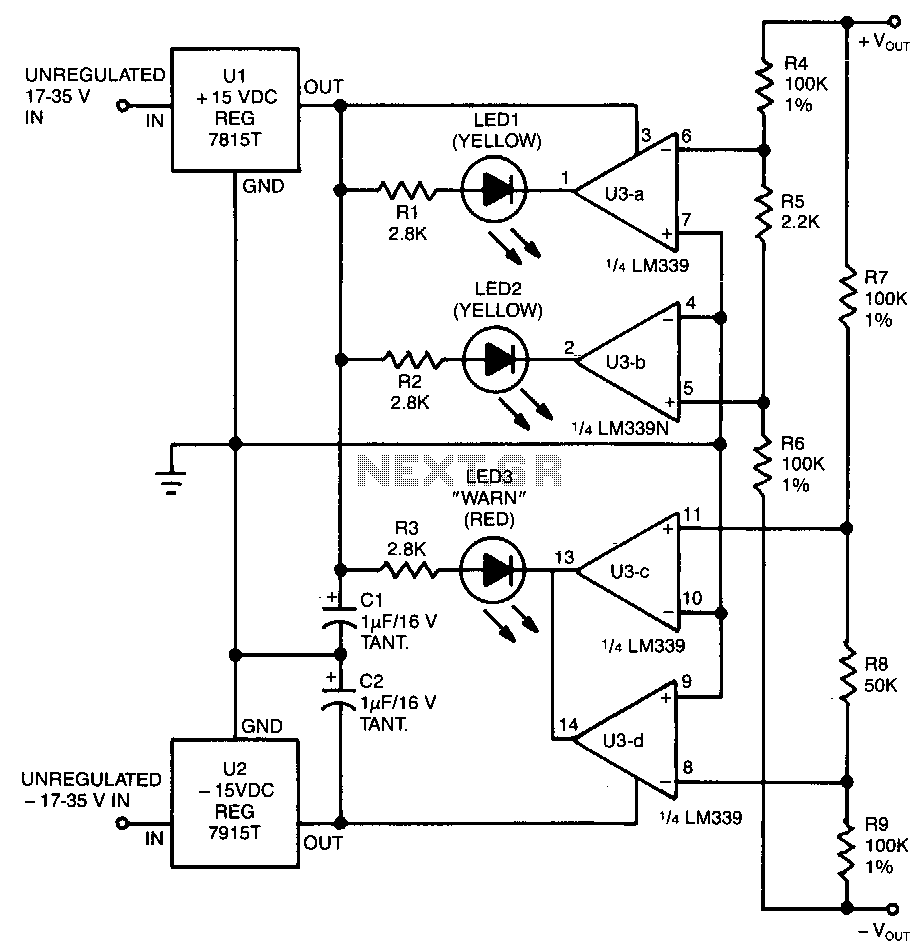
This circuit utilizes two pairs of comparators from an LM339N quad comparator. One pair controls the yellow positive (+) and negative (-) indicators, while the other pair drives the red warning LED3. The circuit is powered by the unregulated section of the power supply. The four comparators receive their switching inputs from two parallel resistor-divider networks. Both networks are connected between the positive and negative output terminals of the power supply. The first network, composed of resistors R4, R5, and R6, divides the input voltage in half, providing output taps at 0.5%. The second network, consisting of resistors R7, R8, and R9, also divides the input voltage in half, with taps at +10%. The 0.5% R4/R5/R6 network drives the two comparators that control the positive and negative indicators (LED1 and LED2). The inputs are configured such that LED2 does not activate until the positive supply exceeds the negative by at least 0.5%, and the positive indicator remains off until the negative supply is at least 0.5% higher than the positive supply. This overlap allows both LEDs to illuminate when the two supplies are balanced within 1% or better. The +10% R7/R8/R9 network drives the other two comparators that manage the warning indicator. If either side of the supply exceeds the other by 10% or more, one of the comparators will switch its output low, activating the red LED3. The LM339N features open-collector outputs, enabling wired OR connections. The inputs for this comparator pair are not crossed, creating a range where neither comparator's output is low, keeping the LED off.
The circuit design employs the LM339N quad comparator, which contains four independent comparators that can be utilized in various configurations. In this specific application, two comparators are dedicated to monitoring the voltage levels of a dual power supply system, ensuring that both supplies are within acceptable limits relative to one another. The use of resistor-divider networks allows for precise voltage scaling, enabling the comparators to respond accurately to variations in supply voltage.
The first voltage divider, comprising R4, R5, and R6, is configured to provide a reference voltage that is half of the input voltage. This reference is critical for determining the operational state of LED1 and LED2. The design ensures that LED2, which indicates the negative supply, only illuminates when the positive supply exceeds it by a defined threshold (0.5%). Conversely, LED1, indicating the positive supply, remains off until the negative supply exceeds the positive by the same threshold. This careful arrangement of thresholds prevents false triggering and allows for a clear visual representation of the supply status.
The second voltage divider, consisting of R7, R8, and R9, is set to provide a reference that is 10% above the nominal voltage. This configuration is essential for the warning indicator LED3. When the difference between the two supplies exceeds 10%, the corresponding comparator will trigger, illuminating the warning LED. The open-collector outputs of the LM339N facilitate the OR logic configuration, enabling multiple comparators to share a common output line for the warning LED.
Overall, this circuit effectively monitors a dual power supply system, providing visual indicators for both normal operation and warning conditions. The design's reliance on comparator thresholds ensures reliable operation while minimizing the risk of false alarms, making it suitable for applications where precise voltage monitoring is essential.This circuit uses two comparator pairs from an LM339N quad comparator; one pair drives the yellow positive (+)and negative (-)indicators, the other jointly drives the red warn LED3. The circuit draws its power from the unregulated portion of the power supply. The four comparators get their switching inputs from two parallel resistor-divider strings. Both~strings have their ends tied between the power supply"s positive and negative output terminals.
The first string, consisting of R4, R5, and R6, divides the input voltage in half, with output taps at 0.5%. The other string, made up of R7, R8, and R9, also divides the input voltage in half, with taps at + lO%.
The 0.5% R4/R5/R6 string drives the two comparators controlling the positive and negative indicators (LEDl and LED2). Their inputs are crossed so that LED2 does not fire until the positive supply is at least 0.5% higher than the negative; the positive indicator does not go off until the negative supply is at least 0.5% higher than the positive-in relative levels.
That overlap permits both LEDs to be on when the two supplies are in 1 % or better balance. The +lOT R7/R8/R9 string drives the other two comparators, which control the warn indicator. If either side of the supply is lO% or more higher than the other, one of the two comparators will switch its output low and light the redLED3the LM339N has opened-collector outputs, allowing such wired OR connections. The inputs are not crossed, as with the other comparator pair, so there is a band in the middle where neither comparators output is low and the LED remains off.
🔗 External reference
Warning: include(partials/cookie-banner.php): Failed to open stream: Permission denied in /var/www/html/nextgr/view-circuit.php on line 713
Warning: include(): Failed opening 'partials/cookie-banner.php' for inclusion (include_path='.:/usr/share/php') in /var/www/html/nextgr/view-circuit.php on line 713