
Power Supply For Amplifier
The power supply circuit for an amplifier is a crucial component that ensures the amplifier operates effectively. It typically consists of a transformer, rectifier, filter, and voltage regulator.
The transformer steps down the AC voltage from the mains supply to a lower AC voltage suitable for the amplifier. This is followed by a rectifier, which converts the AC voltage to pulsating DC. Commonly used rectifiers include full-wave or bridge rectifiers, which provide a smoother DC output.
Next, the filter stage, often composed of capacitors, smooths the pulsating DC to reduce ripple voltage. This filtering is essential for maintaining a stable voltage supply to the amplifier, as excessive ripple can lead to distortion in the amplified signal.
Finally, a voltage regulator may be employed to ensure that the output voltage remains constant despite variations in load or input voltage. Linear regulators or switching regulators can be used, depending on the requirements for efficiency and heat dissipation.
Overall, the design of the power supply for an amplifier circuit must consider factors such as voltage levels, current requirements, and the overall efficiency of the circuit to ensure optimal performance of the amplifier. Proper layout and component selection are also critical to minimize noise and interference in the audio signal.The following circuit shows about Power Supply For Amplifier Circuit Diagram. Features: Easy to build, supported by an adeguate electric response, make a .. 🔗 External reference
Related Circuits
This circuit features a white LED-based emergency light that provides several benefits. It is exceptionally bright due to the incorporation of white LEDs. The light activates automatically when the mains supply is interrupted and deactivates when mains power is...
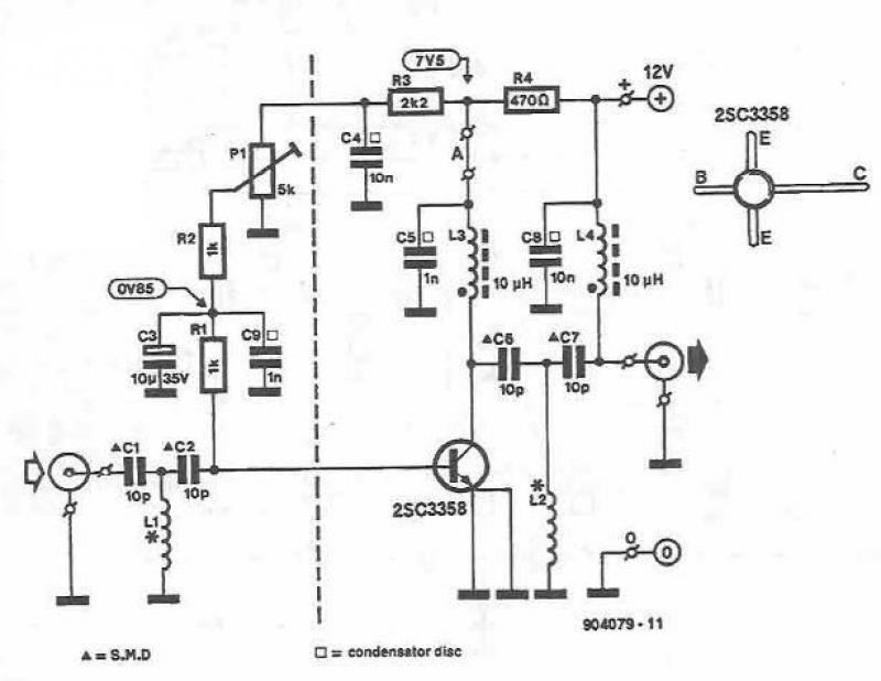
This UHF amplifier circuit project is beneficial for enhancing weak TV signals. The amplifier provides a gain of 10-15 dB within a frequency range of 400 to 850 MHz. To ensure optimal performance and reliability, the PCB tracks should...
Powered by a solar panel, the circuit provides a 5V pure regulated DC voltage. It consists of an oscillator transistor and a regulator transistor. The solar panel charges the battery when sunlight is sufficient to generate a voltage above...
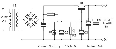
Adjustable Regulated Power Supply 0-15V 1A. The output voltage is stabilized and regulated in the range of 0V to 15V, with a maximum current supply of 1A. The schematic diagram originates from the circuit: Adjustable Regulated Power Supply 0-15V...
Here is a little audio amplifier similar to what you might find in a small transistor radio. The input stage is biased so that the supply voltage is divided equally across the two complimentary output transistors which are slightly...
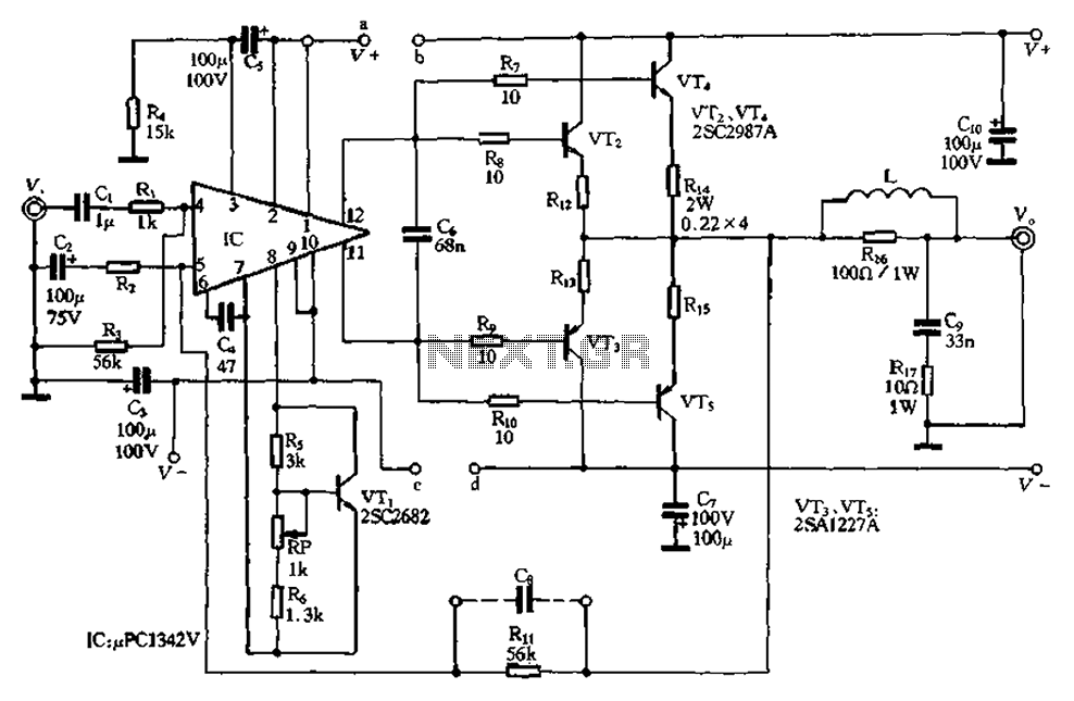
The pLPC1342V and NE are two companies involved in a tube amplifier circuit utilizing 2SA1227A and 2SC2987A transistors, achieving a maximum output power of up to 120W with a cutoff frequency of up to 500 MHz. The circuit, illustrated...