
preamp
High quality microphones also tend to be low impedance, typically around 600 ohms. This is a low input impedance, high quality pre-amplifier of the sort that could be used in a stage mixing desk. In fact that was the purpose for which it was designed, but never used because I soon after left the company.
The circuit uses a dual rail power supply - convenient because there were many op-amps in the machine. Note that Tr1 is a PNP transistor. Theoretically PNP transistors can have lower noise level than NPNs. Tr2 amplifies Tr1`s output. Tr3 is simply a constant current collector load for Tr2, with its current controlled by the 180R emitter resistor.
This can be altered to give more current to feed lower impedance output loads. Overall negative feedback is applied via the 100K pot (log is best) which is the gain control. Note that the feedback loop includes the input and output capacitors so the low frequency response is excellent. The 150K resistor is present to charge up the input and output capacitors to avoid thumps when inserting/withdrawing a microphone.
The voltage across these two capacitors is very small in any case (about 1/2 volt). You can of course do this with an op-amp. One advantage of transistors is that you can easily change a noisy one. Selecting a low noise op-amp may not be so easy. Also of course most constructors will have suitable transistors. You may not have a suitable low noise op-amp to hand! The third circuit is one I was working on as I left the audio company but is seems to be potentially very useful. It should be simple to use it as a low impedance mic amp or as a high input impedance preamp for mic or, with a suitable RIAA equalization, for phono pickup or similar.
It can even be used as a balanced input mic preamp. If you have been browsing this site you may notice that it is the 4 transistor op-amp circuit shown on the index page and at the heart of the low distortion power amplifier. R1 will define the impedance if the high impedance input - say 100K. R4 charges the output capacitor only. R3 defines the operating current in Tr4, say 1K for 500 µA or so. The feedback paths have been separated: d. c. feedback is via the two 100K resistors, which are decoupled so they don`t affect the a. c. feedback. A. c. feedback if via the network Zf, which can be RIAA for phono or whatever as required. Ultrasonics - a page on intruded detectors and remote control has circuits used to amplify sound from microphones for ultrasonics.
These can be adapted for audio use. 🔗 External reference
Related Circuits

This circuit exhibits an exceptionally fast high-frequency response, as demonstrated by applying a 100 kHz square wave to the input. All graphs were produced using Tina Pro. The circuit's design is optimized for high-frequency applications, showcasing rapid response times that...
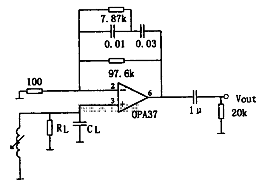
The OPA37 serves as a low-noise preamplifier. The input signal is connected to the inverting input of the OPA37 (pin 3), while the circuit components RL and CL represent the load impedance for electromagnetic pickups. The resistance and capacitance...
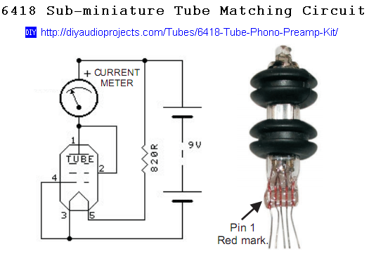
Last year, a low-cost tube stereo headphone amplifier kit from Oatley Electronics (located in New South Wales, Australia) was built and reviewed. This kit gained significant popularity and was sold globally. The headphone amplifier is based on new old...
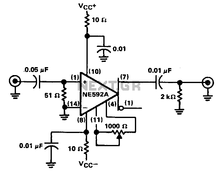
The circuit provides a voltage gain of 20 ±0.1 dB within a frequency range of 500 kHz to 50 MHz. The low-frequency response of the amplifier can be enhanced by increasing the value of the 0.05 µF capacitor connected...
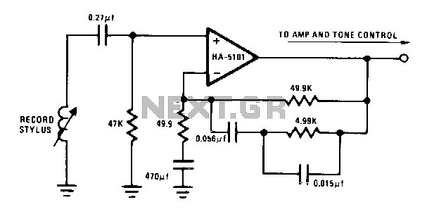
The circuit provides low-frequency boost below 318 Hz and high-frequency attenuation above 3150 Hz. Recent modifications to the response standard include a 31.5-Hz peak gain region to reduce de-oriented distortion from external vibration. The described circuit functions as an audio...
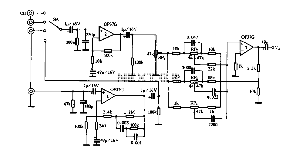
Figure 3 illustrates a circuit featuring the OP37, which is a multi-preamplifier configuration. The OP37 offers superior performance compared to the NE5534 integrated operational amplifier, as indicated in Table 3-3, which contrasts the parameters of both circuits. The table...