
Precise Camera Panning with Stepper Motors

The circuit is based on the PIC16F88 microcontroller, configured for an 8 MHz oscillator with various settings for the watchdog timer, low-voltage programming, power-up timer, and brown-out detection. The LCD is connected to specific pins on the microcontroller, with defined registers and bit settings for data communication. Variables are declared for various functions, including camera control, stepper motor operations, and user input handling. The program includes commands for controlling the stepper motor's movement, managing the camera trigger, and handling remote control inputs for operational commands. The circuit also includes data for configuring the stepper motor's operation, ensuring proper torque development during movement. The implementation of this circuit allows for enhanced functionality and ease of use compared to the previous design.The prototype circuit board used an external LCD display that received commands via an RS-232 interface. Although it worked well programming it was cumbersome. For this reason the circuit board was revised so that it would support a directly attached LCD display.
This view of the back of the board shows the LCD connector more clearly. It also show s the amount of rewiring that was necessary to repurpose the circuit board which was designed for another project. The plug in the lower right goes to the 6 pin stepper motor cable. The USB plug at the left goes to the Canon camera`s USB connection via the connecting cable that came with the camera.
Pressing 1 on the TV remote starts shooting, 2 allows you to adjust the position of the camera and 3 lets you change variable values. Note the that variables are shown in line 4: d=Degrees, s=Steps, p=Pause before / after shot and c=0 for clockwise and c=1 for counterclockwise.
The setting screen allows you to change the variables in the program. Pressing 1 allows you to enter a 4 digit number of degrees X 10. That means to enter 0450 for 45 degrees or 0225 for 22. 5 degrees. The Shoot delay is the pause time before and after a shot is taken. It allows any motion of the tripod to settle and also allows for time exposures. It is a 2 digit number in seconds. If you enter 10 the system will pause for 1/2 of the time (5 seconds) before shooting and an additional 5 seconds after shooting. `9-12-2008 version 3-5 - WORKS `on green speedo board with H-bridge `works properly with 6 wire stepper (old hard drive ) `working well with Hurst motor - 3600 steps per revolution rather than ` advertised 14400 - four steps per pulse, I would guess ` needs pause in "step 1" routine to develop proper torque INCLUDE "modedefs.
bas" cmcon=7 `allows you to use pins as digital rather than analog ansel=0 `allows you to use pins as digital rather than analog @ DEVICE PIC16F88, INTRC_OSC_NOCLKOUT, WDT_OFF, LVP_OFF, PWRT_ON, PROTECT_ON, BOD_ON DEFINE OSC 8 OSCCON = %01100111 `MUST BE USED to set clock speed =$67 = 4mhz DEFINE LCD_DREG PORTB `pins 9-12 on PIC with next item set to "4" DEFINE LCD_DBIT 4 `change to 4 to use top 4 bits (pins 4-7 rather than 0-3) DEFINE LCD_RSREG PORTA DEFINE LCD_RSBIT 1 `pin 18 on PIC with PORTA set DEFINE LCD_EREG PORTA DEFINE LCD_EBIT 0 `pin 17 on PIC with PORTA set p_len VAR BYTE loop VAR BYTE temp0 VAR BYTE temp VAR WORD temp1 VAR WORD temp2 VAR WORD temp3 VAR BYTE temp4 VAR WORD temp5 VAR WORD temp6 VAR BYTE digit VAR BYTE PauseWord VAR WORD TempWord VAR WORD TempWord2 VAR WORD value VAR BYTE LED VAR porta. 2 `also high 10 StartSwitch VAR porta. 5 `pin 2 CameraTrigger VAR porta. 7 `pin 16 - pull high to trigger camera CW VAR BIT `CW if 1, CCW if 0 CW_CCW VAR BIT `stores what was done last line1 CON 128 line2 CON 192 line3 CON 148 line4 CON 212 zero CON 136 one CON 128 two CON 129 three CON 130 four CON 131 five CON 132 six CON 133 seven CON 134 eight CON 135 nine CON 136 channelUP CON 144 channelDOWN CON 145 volumeUP CON 146 volumeDOWN CON 147 OK CON 148 Menu CON 224 ENTER CON 139 Degrees VAR WORD `degrees (steps actually) to move each time NumberOfSteps VAR WORD `number of times to do the rotate ShootSeconds VAR BYTE `pause after completed rotate before shot CWorCCW VAR BIT `0=cw, 1=ccw x VAR BYTE steps VAR WORD stepArray VAR BYTE(4) serial_out VAR porta.
3 vwhole VAR BYTE vdecimal VAR BYTE vwhole=3 vdecimal=7 stepArray[0] = %00001010 `10 stepArray[1] = %00000110 `6 stepArray[2] = %00000101 `5 stepArray[3] = %00001001 `9 TRISb = %11110000 IRpulse_length VAR WORD(13) xx VAR BYTE Command VAR BYTE IRin VAR porta. 4 `pin 15 `ansel = 0 `cmcon0 = 7 trisa. 4=0 `make leds output trisa. 5=1 trisb. 5=0 trisa. 2=1 `start button input trisa. 4=1 `IR input trisa. 3=0 trisa. 7=0 `camera trigger LOW CameraTrigger LOW portb. 0:LOW portb. 1:LOW portb. 2:LOW portb. 3 `relax stepper DATA @0, 1, 194, 0, 8, 1, 1 ` "1, 194"=450 steps=45 deg; 🔗 External reference
Related Circuits
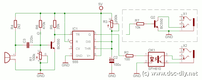
This article describes how to build a simple yet effective sound trigger for cameras or flashes. The circuit allows for experimentation with high-speed photography. The sound trigger circuit is designed to activate a camera or flash unit in response to...
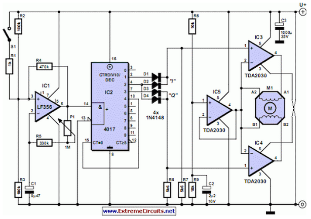
Stepper motors are available in several versions and sizes with a variety of operating voltages. The advantage of this general-purpose controller is that... Stepper motors are electromechanical devices that convert electrical energy into precise mechanical movement. They are widely used...
This circuit leads palmorefmata coils, engine. Each coil is driven by a transistor type Darlington. Darlington Transistors internally comprise two transistors connected in series. The "hfe" Darlington is equal to the multiplication of "hfe" of both its internal transistor....
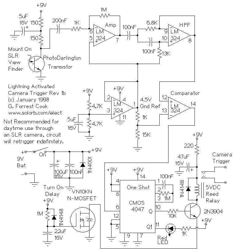
This circuit is used to trigger a camera's electronic shutter circuit when a flash of lightning is present. This circuit would also work for photographing fireworks displays or other events involving flashes of light. More: In a nutshell, the...
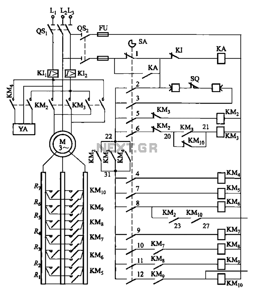
The system is managed by the master controller LKl-12/90 and a magnetic disk control unit PQR10A, which includes a control circuit. The cam control device SA is responsible for contact closure, as indicated in Table 8-5. The main electrical...
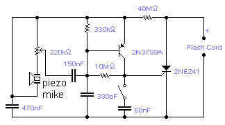
If you wish to take a picture of a fleeting event which generates a sound, you can do it with this sound activated trigger. It does not require any power supply: it feeds on the high voltage available on...
Warning: include(partials/cookie-banner.php): Failed to open stream: Permission denied in /var/www/html/nextgr/view-circuit.php on line 713
Warning: include(): Failed opening 'partials/cookie-banner.php' for inclusion (include_path='.:/usr/share/php') in /var/www/html/nextgr/view-circuit.php on line 713