
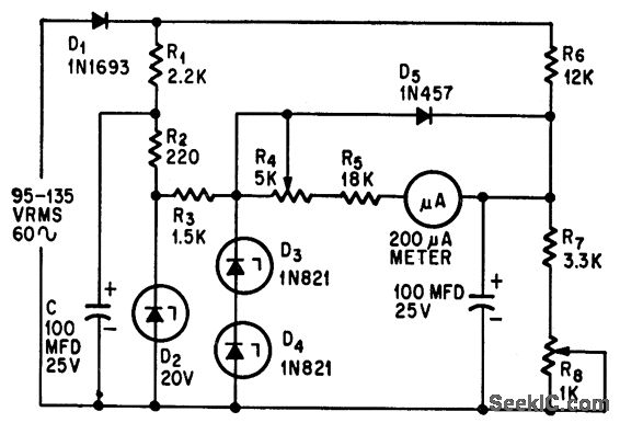
PRECISION AC VOLTMETER
The circuit design leverages the properties of Zener diodes to enhance measurement accuracy significantly. The basic principle involves using a Zener diode to establish a precise reference voltage, which compensates for the inherent inaccuracies of the measuring device. In this configuration, the Zener diode is connected in reverse bias to maintain a constant voltage across its terminals, which serves as a reference point for the measurements.
The AC voltage to be measured is first rectified using a full-wave rectifier circuit, which converts the alternating current into direct current (DC). This rectified voltage is then scaled down to a suitable level for the meter using a voltage divider network. The values of the resistors in the divider are chosen based on the expected input voltage range and the desired output voltage to ensure that the meter operates within its optimal range.
The output from the voltage divider is compared to the reference voltage provided by the Zener diode. Any deviation from the reference voltage indicates a variation in the measured AC voltage. This feedback loop allows for adjustments to be made, thereby improving the overall accuracy of the measurement.
The circuit may include additional components such as capacitors for filtering noise and transient spikes, ensuring that the readings are stable and reliable. The final output can be displayed on a digital voltmeter or an analog meter, depending on the application requirements.
Overall, this circuit design not only enhances the measurement accuracy of AC voltages but also demonstrates the practical application of Zener diodes in electronic measurement systems.Measures a-c voltages between 95 and 135 v with 0. 6% accuracy while using ordinary 2% accuracy meter. Zener diodes provide reference voltage. -D. S. Belanger, Simple Circuit Increases Measurement Accuracy, Electronics, 38:22, p 69. 🔗 External reference
Related Circuits
This circuit greatly expands upon the capabilities of circuit 02. A thermocouple signal is quite small, and the long thermocouple leads often induce quite a bit of noise into the system. This new circuit is far more accurate, stable,...
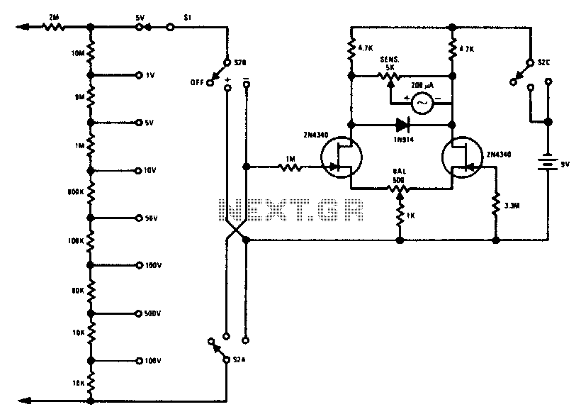
This FETVM replaces the function of the VTVM while eliminating the need for a traditional line cord. Additionally, it offers significantly improved drift rates compared to vacuum tube circuits, enabling a 0-volt full-scale range that is generally impractical with...
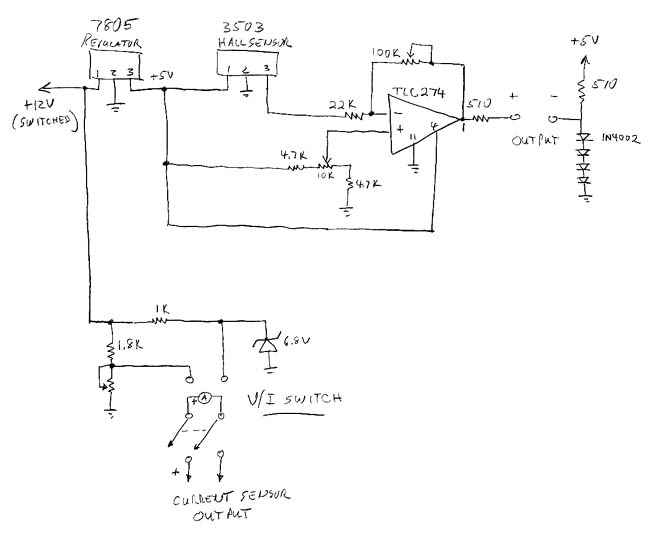
The sprite, which is experiencing an additional electrical load from an electric cooling fan, is barely maintaining battery charge. To address this issue, an electronic voltage regulator is planned; however, monitoring the charging process is essential before making any...
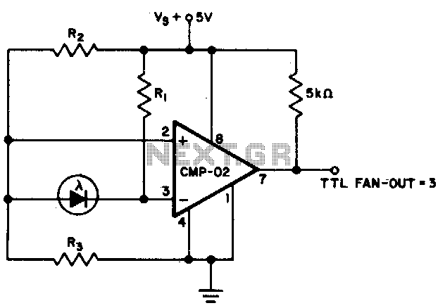
The output state changes at a photodiode current of 0 µA. For R1 = 2 MΩ, R2 = R3 = 5 MΩ. The described circuit likely involves a photodiode used in conjunction with resistors R1, R2, and R3 to create...
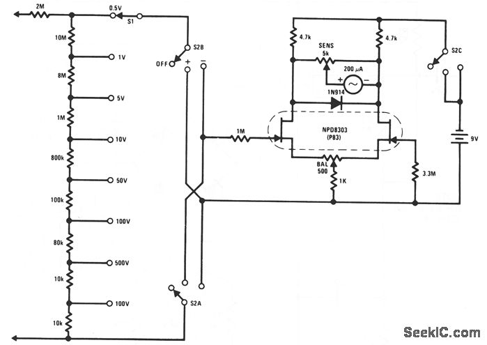
This FET voltmeter (FETVM) serves as a replacement for the vacuum tube voltmeter (VTVM) and eliminates the need for a standard line cord. Additionally, the drift rates of field-effect transistors (FETs) are significantly better than those of vacuum tube...

This design circuit is for a digital voltmeter. The integrated circuit ICL7107 serves as a 3-1/2 digit LED analog-to-digital converter (A/D converter). It includes an internal voltage reference, high isolation analog switches, sequential control logic, and display drivers. An...