
Precision current sink sourcel
The operational amplifier circuit described operates effectively within specified voltage and current parameters, ensuring reliable performance across a range of conditions. The operational amplifier is configured to maintain a constant voltage output, which is crucial for applications requiring stable power supply. The inclusion of transistors T3 and T4 allows for current limiting, protecting the circuit from overload conditions.
The unijunction transistor (Q1) serves as the timing element, generating pulses that can be precisely controlled to achieve the desired flash rate of the LED. This feature is particularly useful in applications such as visual indicators or signaling devices. The low current draw of 2mA at a flash rate of 12 flashes per second indicates efficient power usage, making this circuit suitable for battery-operated devices.
The optical isolator plays a critical role in safeguarding sensitive components, such as microprocessors, from voltage spikes that can occur when switching inductive loads. This protection is vital for ensuring the longevity and reliability of electronic systems. The use of an RC filter with a Darlington transistor pair enhances the reset speed of the printing magnet, facilitating rapid operation in teleprinter applications.
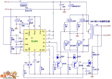
Overall, this circuit design exemplifies a well-thought-out approach to combining various electronic components to achieve a robust and efficient operational amplifier-based system. The careful consideration of parameters and protective measures ensures that the circuit operates effectively in diverse environments and applications.Adopted operation amplifier can obtain constant voltage source with high amplification factor and large load current, when the circuit parameter has great change, the output voltage still have high precision. The output current limit is undertaken by T3, T4 and positive feedback circuit which is composed of operation amplifier.
The technical param eters of this circuit: input voltage: UE=7~18V; maximum output voltage: Umax=UE-2V; maximum load current: Imax=5A. (View) The oscillator which is composed of unijunction transistor Q1 will produce a series of timing pluse triggering thyristor, and then the thyristor drives red LED.
When the flash speed is 12/s, the work current is only 2mA. (View) When the switch teleprinter is inductive load, optical isolator provides teleprinter, 8080A or other microprocessors with protection transit. RC filter with darlington transistor pair accelerates the reset of printing magnet. (View) 🔗 External reference
Related Circuits
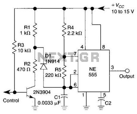
A 1-kHz gated oscillator with no long turn-on cycle is shown. R2, R3, and D1 preset the voltage on tuning capacitor C1 to a percentage of the supply voltage. The circuit described functions as a gated oscillator operating at a...
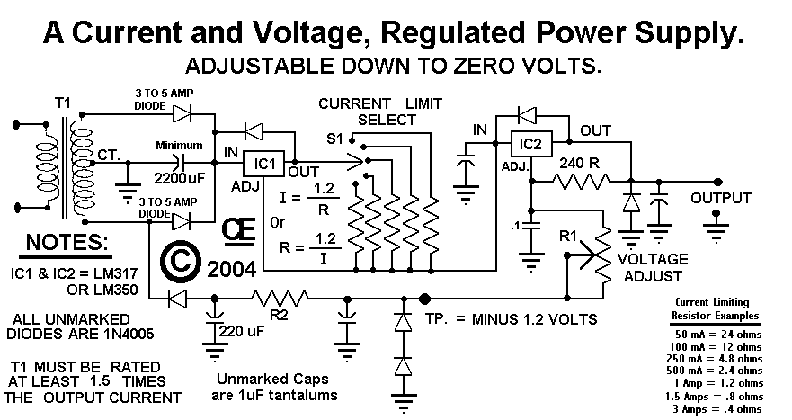
This circuit employs a rotary switch to select various current ranges, as using a potentiometer is not practical for lower resistance and high current ranges. However, a potentiometer can be utilized for lower current ranges, with the lowest switch...
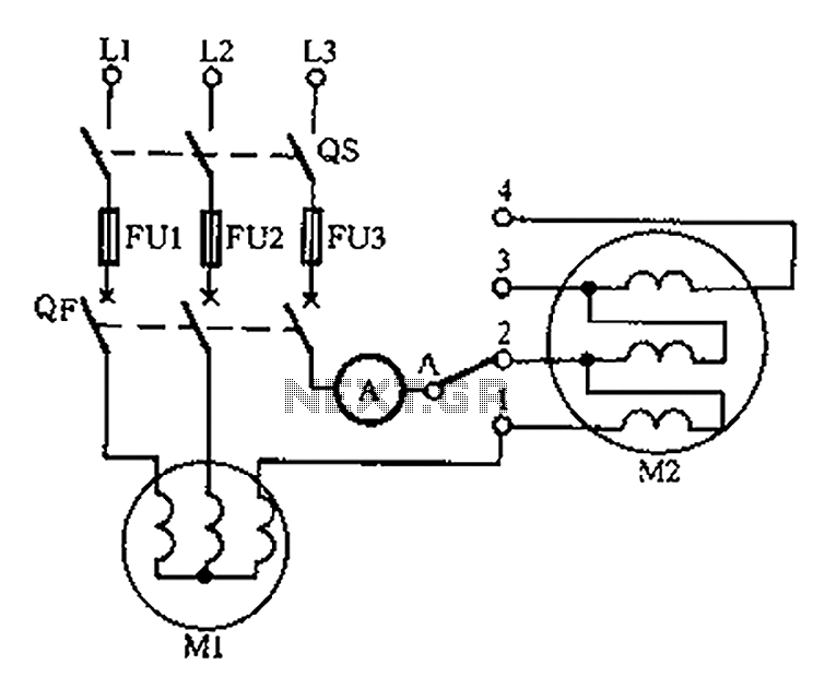
Below is a circuit diagram for detecting motor winding current imbalance during the drying process. The circuit diagram is designed to monitor the current flowing through the windings of a motor used in drying applications. This imbalance detection is crucial for...
A 567 IC tone decoder/detector can be utilized to construct a remote control or intercom system. This circuit is capable of controlling a relay or transmitting an audio signal. The 567 IC is a versatile integrated circuit designed for tone...
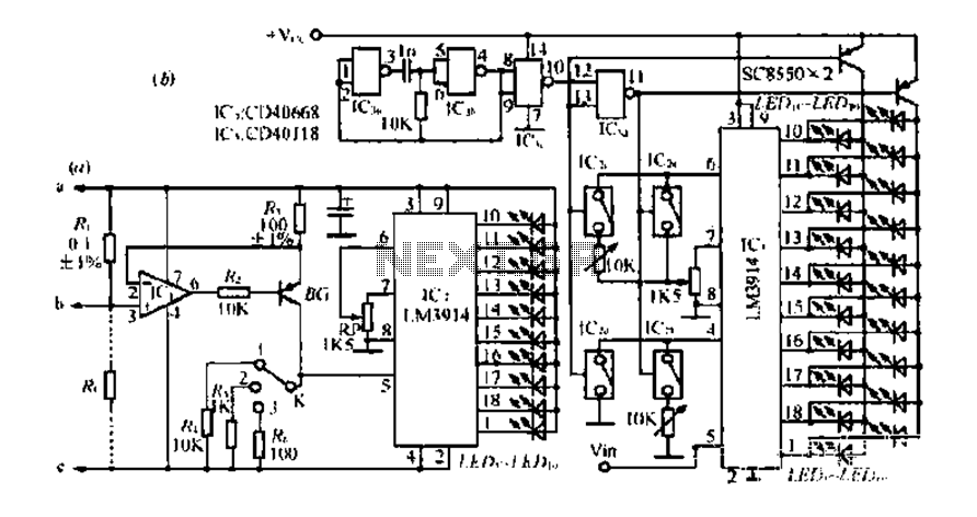
Figure A, B, and C illustrate the test rod end clip, with a positive power supply terminating test equipment. The B and C ends are connected in series with the load, where C represents the negative side of the...
This circuit is a two-wire light level detector. The power supply and output signal are delivered through the same wires, utilizing a current loop. This two-wire light level detector circuit operates by using a single pair of wires for both...
Warning: include(partials/cookie-banner.php): Failed to open stream: Permission denied in /var/www/html/nextgr/view-circuit.php on line 713
Warning: include(): Failed opening 'partials/cookie-banner.php' for inclusion (include_path='.:/usr/share/php') in /var/www/html/nextgr/view-circuit.php on line 713