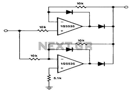
Precision-full-wave-rectifier

This circuit provides accurate full-wave rectification. The output impedance is low for both input polarities, and the errors are small at all signal levels. It is important to note that the output will not sink heavy currents, except for a small amount through the 10 kΩ resistors. Therefore, the load applied should be referenced to ground or a negative voltage. The reversal of all diode polarities will reverse the polarity of the output. Since the outputs of the amplifiers must slew through two diode drops when the input polarity changes, the 741-type devices exhibit 5% distortion at approximately 300 Hz.
This circuit utilizes a full-wave rectification method to convert alternating current (AC) signals into direct current (DC) signals, ensuring that the output voltage maintains a consistent polarity regardless of the input signal's phase. The low output impedance characteristic of the circuit allows for effective signal transfer, minimizing the voltage drop and ensuring that the output remains stable across various load conditions. The design includes 10 kΩ resistors that play a crucial role in limiting the current that the circuit can sink, thus preventing potential damage to the components while maintaining performance.
The circuit's design is sensitive to the orientation of the diodes used; reversing the polarities of the diodes will result in a corresponding reversal of the output voltage polarity. This feature is significant for applications requiring adjustable output characteristics based on the input configuration.
Additionally, the inclusion of 741-type operational amplifiers in this circuit introduces a level of distortion that must be considered in precision applications. The amplifiers experience a slew rate limitation, particularly when the input signal polarity changes, as they must overcome the forward voltage drops of two diodes. This results in a distortion level of approximately 5% at a frequency of 300 Hz, which may be acceptable in certain applications but could be problematic in high-fidelity systems.
In summary, this full-wave rectifier circuit is designed for efficient signal processing with low output impedance and minimal distortion, making it suitable for various electronic applications where reliable DC output is required from an AC input. Proper consideration of component specifications and configurations is essential to optimize performance and ensure the desired operational characteristics.This circuit provides accurate full-wave rectification. The output impedance is low for both input polarities, and the errors are small at all signal levels. Note that the output will not sink heavy currents, except a small amount through the 10-K!J resistors.
Therefore, the load applied should be referenced to ground or a negative voltage. The reversal of all diode polarities will reverse the polarity of the output. Since the outputs of the amplifiers must slew through two diode drops when the input polarity changes, the 7 41-type devices give 5% distortion at about 300Hz.