
precision high voltage regulator
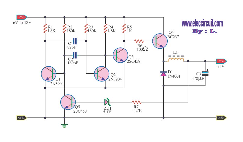
This precision high voltage regulator is designed to convert a 9 V input from a battery into a stable 5 V output. The circuit utilizes a switching regulator topology, which is known for its efficiency in power conversion. The regulator achieves an efficiency of 80%, making it suitable for battery-operated applications where power conservation is critical.
The core component of this circuit is the transistor Q1, which serves as the main switching element. When Q1 is turned on, it allows current to flow from the input to the output. The collector voltage of Q1 rises as it conducts, which is essential for maintaining the desired output voltage. The switching action minimizes power loss, as the transistor operates in a saturation region during the 'on' state, effectively reducing heat generation.
To ensure stable operation, additional components such as inductors and capacitors may be integrated into the circuit. These components help filter the output voltage and smooth out any fluctuations caused by the switching action. The inductor stores energy when the transistor is on and releases it when the transistor is off, contributing to the regulation of output voltage.
The output capability of 50 mA indicates the maximum current that the regulator can supply to a load, making it suitable for powering low-power electronic devices. The design can be further optimized by selecting appropriate values for the inductance and capacitance to enhance performance characteristics such as transient response and load regulation.
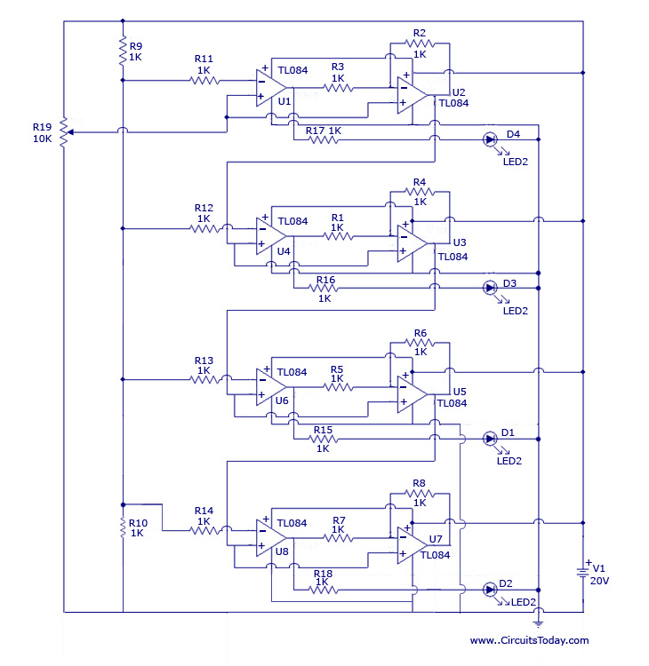
In summary, this high voltage regulator circuit is a compact and efficient solution for converting 9 V battery power into a stable 5 V output, utilizing a simple switching mechanism to achieve high efficiency and reliable performance for various electronic applications.Precision high voltage regulator power supply. Go to that page to read the explanation about above power supply related circuit diagram. This simple switching regulator circuit have 5 V output, the input provide by a 9 V battery. Ithaving 80% efficiency and 50mA output capability. How simple switching Regu lator works: While Q1 is actually on, its collector voltage increases, delivering current. 🔗 External reference
Related Circuits
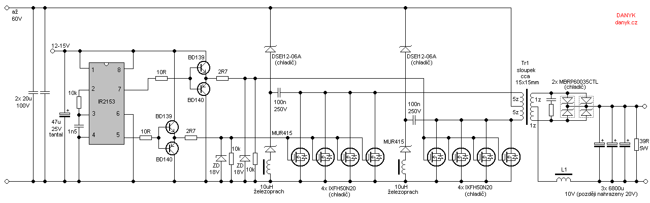
Occasionally, a low voltage power supply capable of delivering very high currents (hundreds of amperes) is required for applications such as spot welding, heating or melting metals, starting vehicle engines, or conducting various physical experiments. A decision has been...
The circuit reduces voltage size or functions as a step-down voltage converter circuit, which is a DC regulated circuit model utilizing a switching converter. This design generates a specific voltage output. The step-down voltage converter, also known as a buck...
After the battery is connected, the movement of the touch stick activates the light source, which illuminates the photosensitive tube and generates a light current. This triggers the first level 3DG6 to turn on, allowing the emitter to output...
The design originated from the interest in discovering a new technique for analog to digital conversion. The two types of ADC (Analog to Digital Converter) that influenced the development of this circuit are the Flash Type ADC and the...
Here they exist two regulator circuits, that use the IC L200, as regulator of voltage and current, the company SGS-Thomson, which give these circuits. In circuit Fig.1, we can regulate the output voltage, with the RV1, while in the...
This is a specialized low-voltage version of an audio preamplifier. The emitter voltage of transistor T1 is biased close to half the supply voltage (1.5V) to enable maximum output voltage swing. Both transistors are directly coupled and utilize closed-loop...
Warning: include(partials/cookie-banner.php): Failed to open stream: Permission denied in /var/www/html/nextgr/view-circuit.php on line 713
Warning: include(): Failed opening 'partials/cookie-banner.php' for inclusion (include_path='.:/usr/share/php') in /var/www/html/nextgr/view-circuit.php on line 713