
Precision Measurement without Ground Offsets Using Differential Amplifier Input to A/D ADC
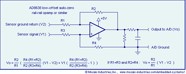
In electronic systems, ground loop offset errors and ground noise can significantly impact the accuracy of measurements, particularly in applications involving non-isolated sensors. To mitigate these issues, a differential amplifier or instrumentation amplifier is employed prior to the A/D conversion process. This approach leverages the differential input characteristics of these amplifiers to reject common-mode signals, which are often the source of ground loop errors.
The differential amplifier configuration typically consists of two input terminals that receive the signal from the sensor and a reference ground. By amplifying the difference between these two inputs while rejecting any signals that are common to both, the differential amplifier effectively eliminates the influence of ground loops. This feature is crucial for maintaining measurement integrity in environments where multiple devices share a common ground.
Instrumentation amplifiers, which are a specialized form of differential amplifiers, provide additional benefits such as higher input impedance and better common-mode rejection ratios (CMRR). These attributes make instrumentation amplifiers particularly suitable for precise measurements in medical devices, industrial sensors, and other applications where accuracy is paramount.
In simpler applications, a basic op-amp circuit can also be designed to remove ground loop errors. This circuit typically includes feedback mechanisms that stabilize the output and enhance the accuracy of the measurement. The schematic for this op-amp configuration may include resistors and capacitors to set the gain and bandwidth, ensuring that the circuit operates effectively in the desired frequency range.
Overall, the implementation of differential or instrumentation amplifiers, along with carefully designed op-amp circuits, plays a critical role in achieving reliable and accurate signal processing in electronic measurement systems. By addressing ground loop errors and noise, these amplifiers enable high-quality data acquisition necessary for modern electronic applications.Ground loop offset errors and ground noise are removed by a differential amplifier or instrumentation amplifier prior to A/D analog to digital conversion. The differential input amplifier mitigates ground loop errors. Precision measurement of non-isolated sensors. Simple op-amp circuit removes ground loop errors. Op-amp schematic removes ground noise.. 🔗 External reference
Related Circuits
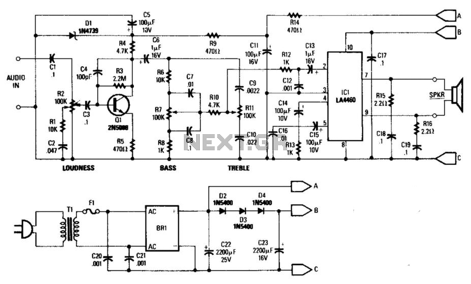
This general-purpose low-power (5 W) audio amplifier is designed to drive speakers ranging from 8 to 12 inches. It utilizes a Sanyo LA4460 integrated circuit (IC) as the audio output component. The circuit features a loudness control, a driver...
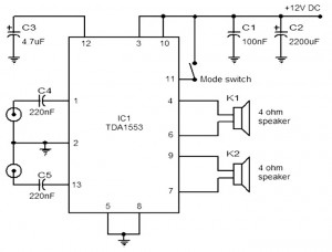
The provided schematic represents a car stereo amplifier circuit that can be utilized in cars or other vehicles. The circuit is based on the TDA1553, which is a Class-B audio amplifier. This circuit is straightforward, consisting solely of the...
An average ability amplifier characterized by acceptable overall quality, while being simple in construction. It is frequently used in live loudspeakers. The design incorporates high-quality FET transistors, specifically HEXFET technology, which are voltage-controlled rather than conventional bipolar transistors. The...

This notch filter is beneficial for tunable band-reject applications in the audio range. The specified values will provide a tuning range of approximately 300 to 1500 Hz. The notch filter is designed to attenuate a specific frequency while allowing others...
This decibel meter circuit responds to sound pressure levels ranging from approximately 60 to 70 dB (decibels). The sound is captured by an 8-ohm speaker and amplified using a transistor stage along with an LM324 operational amplifier section. A...
The CL type circuit is not a power amplifier output capacitance, feedback capacitance, or compensation capacitor amplifier circuit; it operates solely through a transistor (or FET) and a resistor. This circuit can generate feedback, and phase shift elements are...
Warning: include(partials/cookie-banner.php): Failed to open stream: Permission denied in /var/www/html/nextgr/view-circuit.php on line 713
Warning: include(): Failed opening 'partials/cookie-banner.php' for inclusion (include_path='.:/usr/share/php') in /var/www/html/nextgr/view-circuit.php on line 713