
Precision Monostable Multivibrator Circuit
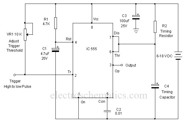
The CD4538 monostable multivibrator circuit is designed for applications where precise timing is essential. The circuit configuration typically includes the IC, a resistor (R1), and a capacitor (C1) to define the timing characteristics. The timing interval, which is determined by the RC time constant, can be calculated using the formula T = 0.7 * R1 * C1, where T is the time duration for which the output remains low.
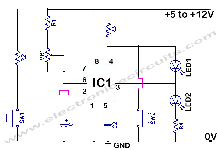
In operation, upon powering the circuit, the output of the CD4538 is high, indicating that the circuit is ready to accept a trigger. The trigger is applied through pin 5, which is connected to the switch S1. When S1 is pressed, it sends a low-to-high transition pulse to the trigger pin, causing the output to drop low and remain in that state for the duration defined by the RC components.
The output pin of the CD4538 can be connected to a PNP transistor (T1), which acts as a switch for the load. The load can be an LED, which will turn on during the low output state of the IC, or a buzzer that will sound for the same duration. The PNP transistor is biased correctly to ensure that it turns on when the output of the CD4538 is low, allowing current to flow through the load.
This circuit can be utilized in a variety of applications, including timers, pulse generators, and event counters, where accurate timing control is paramount. The flexibility of adjusting R1 and C1 values allows for easy customization of the timing interval to suit specific requirements. Additionally, the CD4538's immunity to false triggering enhances the reliability of the circuit in practical applications.A monostable multivibrator using IC CD4538. It is a precision monostable/astable multivibrator IC free from false triggering. This can be used for various application in which precise timing cycle is required. CD4538 is the precision monostable/astable multivibrator IC that is free from false triggering. It is more reliable than the popula r timer IC 555. Here the IC is wired as a short duration monostable timer using R1 and C1 as timing components. With the given values, output of IC1 remains low for three minutes. By changing the value of C1 or R1 various time intervals can be obtained. Unlike 555 IC in the monostable mode, here in CD4530, output of IC becomes high at power on and becomes low when the trigger pin5 gets a low-to-high transition pulse. When S1 is pressed, the high going pulse triggers IC and its output goes low. This drives the load through the PNP transistor T1. Load can be an LED, Buzzer etc. 🔗 External reference
Related Circuits
The color of the LED makes a significant difference. The type and size of the LED, such as 3mm or 5mm, and the power source are crucial factors to consider. More information is required for accurate calculations. A basic...
This is a variation on the astable multivibrator. Circuit was recently developed to test for N-mosfets (the power kind e.g. irf830). I don't claim circuit can test all bad mosfets or all fault mosfet conditions. If mosfet is working...

The infrared remote-control tester employs a sensitive PN-type solar sensor directly connected to a Darlington amplifier composed of transistors Q1 and Q2. Biasing is achieved through resistor R1 and PI, a variable resistor that functions as a sensitivity control....
Infrared remote controls are using a 32-56 kHz modulated square wave for communication. These circuits are used to transmit a 1-4 kHz digital signal (OOK modulation) through infra light (this is the maximum attainable speed, 1000-4000 bits per sec)....

This circuit is similar to the one found in the Single Buss 1V/Octave Keyboard Controller. Refer to the circuit description there for more details. This board includes additional resistors used in the keyboard voltage divider. In a typical keyboard,...
The 555 Timer Time Delay Circuit uses LEDs to visually indicate the status of the circuit at any moment. The operation begins when the reset switch, SW2, is activated. The 555 Timer is a versatile integrated circuit widely used for...