
PRECISION RECTIFIER
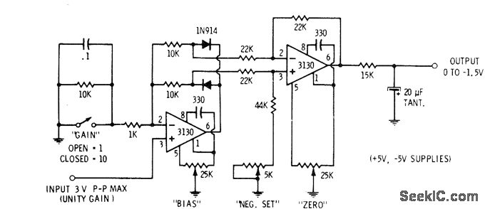
The described circuit operates as a full-wave rectifier using two stages of operational amplifiers to achieve precise signal processing. The first stage employs the 3130 op-amp to perform signal separation based on polarity, effectively allowing the circuit to handle both halves of the input AC waveform. The use of two 10K resistors helps ensure that the op-amp can accurately differentiate between positive and negative signal components, providing a robust method for signal conditioning.
The subsequent stage of the circuit integrates the outputs from the first stage, where the second op-amp combines the rectified peaks. The 5K trimming potentiometer is a critical component for calibrating the circuit; it allows for fine-tuning of the amplitude of the output signal, ensuring that both the positive and negative peaks are matched in height. This adjustment is essential for maintaining accuracy in applications where precise voltage measurements are required.
The output of the second op-amp stage presents a negative-going full-wave replica of the original input signal. This characteristic is particularly useful in digital voltmeter applications, where the goal is to convert the AC input into a stable DC representation. Following this stage, a filtering process is employed to smooth out the output, resulting in an average DC voltage that can be easily interpreted by subsequent measurement systems. The specified range of 0 to -1.5 V for a 0-3 V peak-to-peak input indicates the circuit's capability to handle typical voltage levels encountered in various electronic applications, making it an effective solution for accurate voltage measurement and analysis.Used in digital voltmeters to convert AC waveform to full-waverectified DC equivalent. First 3130 opamp is used as polarity separator, with negative-going signals appearing across upper 10K resistor and positive-going signals across lower 10K resistor. Output of opamp exceeds these voltage drops by exactly diode voltage drop. Second opamp stage re combines positive and negative peaks. 5K trimming pot is adjusted so both peaks are equal height. Output of second opamp is negative-going full-wave replica of input signal. After filtering, output is average DC value in range from 0 to -1. 5 V for 0-3 V P-P input. -D. Lancaster, "CMOS Cookbook, " Howard VV. Sams, Indianapolis, IN, 1977, p 345-346. 🔗 External reference
Related Circuits
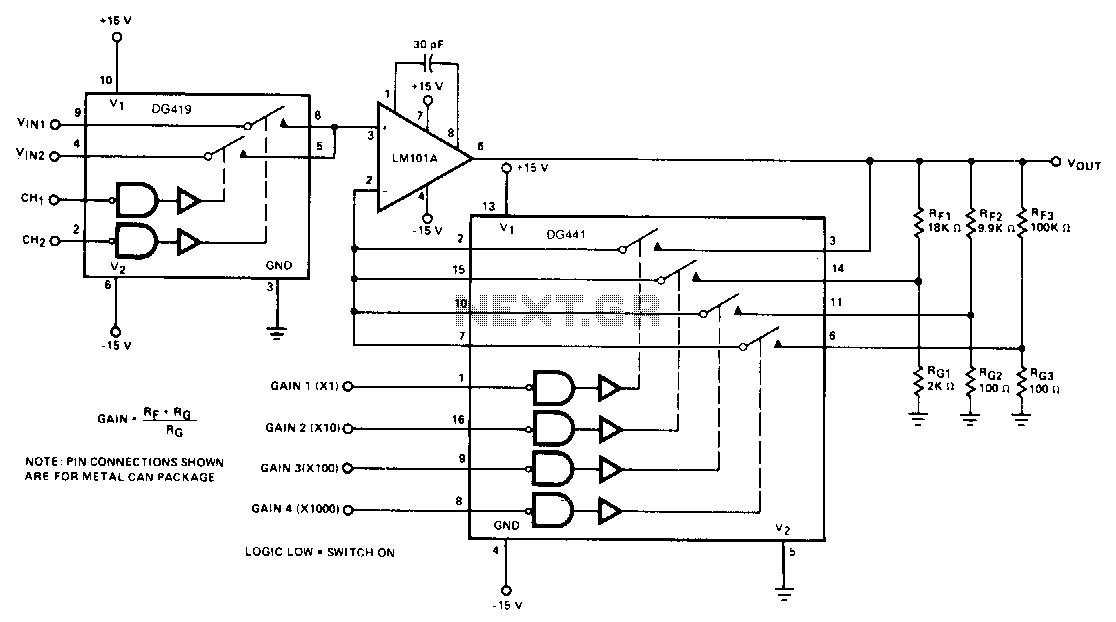
The DG419 considers the high input impedance of the operational amplifier, making the effects of Rvs negligible. The DG441 is also connected in series with RIN and is not included in the feedback dividers, thereby contributing negligible error to...
The RH1078M is a micropower dual operational amplifier in a standard 8-pin configuration. This device is optimized for single supply operation at 5V, with specifications also available for ±15V. Linear Technology provides numerous demo boards at no cost to...
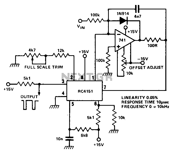
The RC 4151 precision voltage-to-frequency converter generates a pulse train output that is linearly proportional to the input voltage. The RC 4151 is a highly accurate voltage-to-frequency converter designed for applications requiring precise frequency output based on varying voltage levels....
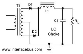
A circuit that utilizes both positive and negative alternations in an alternating current to generate direct current. There are two types of full-wave rectifier circuits: one that employs two diodes and requires a center-tapped transformer, and another that uses...
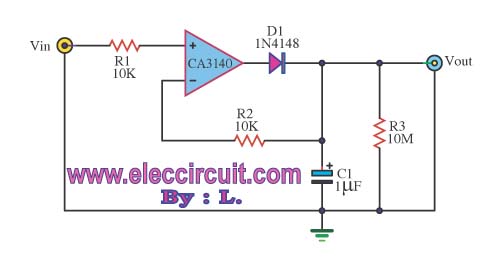
This circuit is designed to check the peak voltage of a signal that can change at any time. Measuring with a multimeter is insufficient for this purpose, hence the recommendation for this circuit. It operates with a positive signal...
The LM3361A features a complete narrowband FM demodulation system that operates at supply voltages of less than 2V. The device includes several blocks such as an oscillator mixer, FM IF limiting amplifier, FM demodulator operational amplifier, scan control, and...
Warning: include(partials/cookie-banner.php): Failed to open stream: Permission denied in /var/www/html/nextgr/view-circuit.php on line 713
Warning: include(): Failed opening 'partials/cookie-banner.php' for inclusion (include_path='.:/usr/share/php') in /var/www/html/nextgr/view-circuit.php on line 713