
Pressure Sensor Alarm
The simple pressure sensor alarm circuit typically includes a pressure sensor, an operational amplifier (op-amp), a resistor, a transistor, a buzzer or alarm, and a power supply. The pressure sensor detects changes in pressure and converts this physical change into an electrical signal. This signal is then amplified by the op-amp to ensure it is strong enough to trigger the subsequent components in the circuit.
The resistor is used to set the gain of the op-amp, allowing for precise control over the sensitivity of the pressure detection. The output from the op-amp is connected to the base of the transistor, which acts as a switch. When the amplified signal exceeds a certain threshold, the transistor is activated, allowing current to flow through the buzzer or alarm, thereby alerting users to the change in pressure.
The power supply for this circuit can typically range from 5V to 12V, depending on the specifications of the components used. It is essential to ensure that all components are rated for the voltage and current levels present in the circuit to avoid damage and ensure reliable operation.
The design of this circuit can be easily modified to suit specific applications by adjusting the sensitivity and the type of alarm used. For instance, a different type of sensor could be incorporated for varying pressure ranges, or the buzzer could be replaced with an LED for visual indication. Overall, this simple pressure sensor alarm circuit is an effective solution for monitoring pressure changes in various applications, such as in hydraulic systems, pneumatic systems, or even in safety applications where pressure levels are critical.General purpose circuit of the simple pressure sensor alarm is built around a couple of readily available cheap components. Working of this circuit is str.. 🔗 External reference
Related Circuits
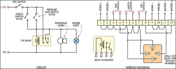
This cost-effective burglar alarm utilizes a 12V strobe light and a truck reversing horn as the visual and audible alarm outputs. The alarm mechanism consists of a 12V horn relay and several pressure mat switches. This straightforward design ensures...

The high-temperature alarm will emit a beep and the LED will blink when the temperature of the device rises abnormally. This simple overheating alarm is designed to monitor heat levels. The high-temperature alarm circuit is an essential safety device used...

This is a single-zone alarm system equipped with automatic exit, entry, and siren cut-off timers. It supports various types of normally-closed input devices, including magnetic reed contacts, foil tape, and passive infrared sensors (PIRs). The circuit is designed to...
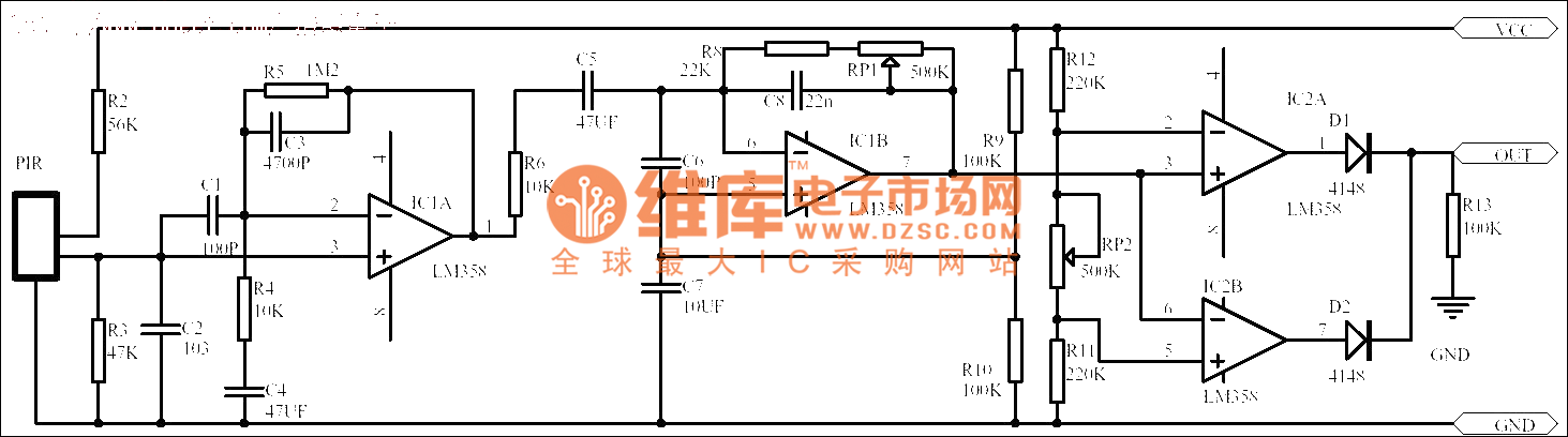
Passive human body infrared sensor circuits are generally similar in design, although some may have fewer stages. The circuit illustrated is sourced from the NICERA manufacturer and is considered a classic example. The front-end stage consists of a low-frequency...
After attempting to use this reportedly "pretty good" microphone in a variety of situations with some "pretty bad" results, I dissected the power supply and found the same audio transformer that’s in their 180-in-one project kits! This DAT-Heads Digest...
The SB0061 is a pyroelectric sensor module designed for human body detection. It integrates a PIR (Passive Infrared) detector with a Fresnel lens on a compact printed circuit board (PCB), along with an analog integrated circuit (IC) identified as...
Warning: include(partials/cookie-banner.php): Failed to open stream: Permission denied in /var/www/html/nextgr/view-circuit.php on line 713
Warning: include(): Failed opening 'partials/cookie-banner.php' for inclusion (include_path='.:/usr/share/php') in /var/www/html/nextgr/view-circuit.php on line 713